Air cleaner for portable engine

a portable, air cleaner technology, applied in the direction of instruments, mechanical control devices, separation processes, etc., can solve the problems of increasing the cost and weight of the air cleaner, and achieve the effect of reducing manufacturing and assembly costs, facilitating idling speed adjustment, and increasing rigidity of the air cleaner

Inactive Publication Date: 2008-05-13
KAWASAKI HEAVY IND LTD
View PDF16 Cites 4 Cited by
  • Summary
  • Abstract
  • Description
  • Claims
  • Application Information

AI Technical Summary

Benefits of technology

[0009]Accordingly, it is an object of the present invention to provide an air cleaner for a portable engine which is able to solve the foregoing problems.

Problems solved by technology

As a result, the cost and the weight of the air cleaner 13 increase.

Method used


Image

  • Air cleaner for portable engine
  • Air cleaner for portable engine
  • Air cleaner for portable engine

Examples


Embodiment Construction

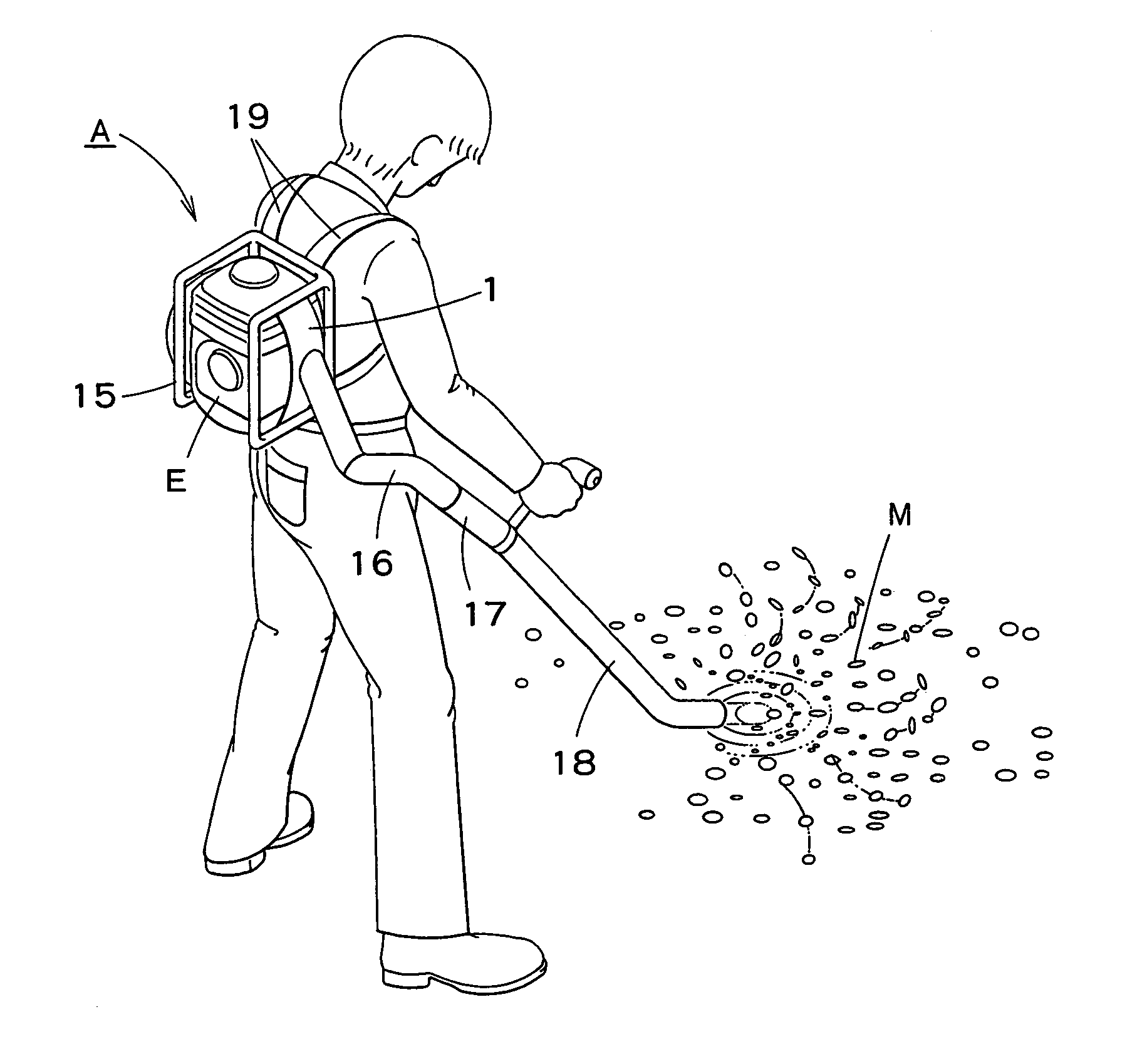
[0038]An air cleaner according to an embodiment of the present invention will be described with reference to the drawings as applied to an engine E included in a backpack blower as shown in FIG. 9.

[0039]Blower and Engine

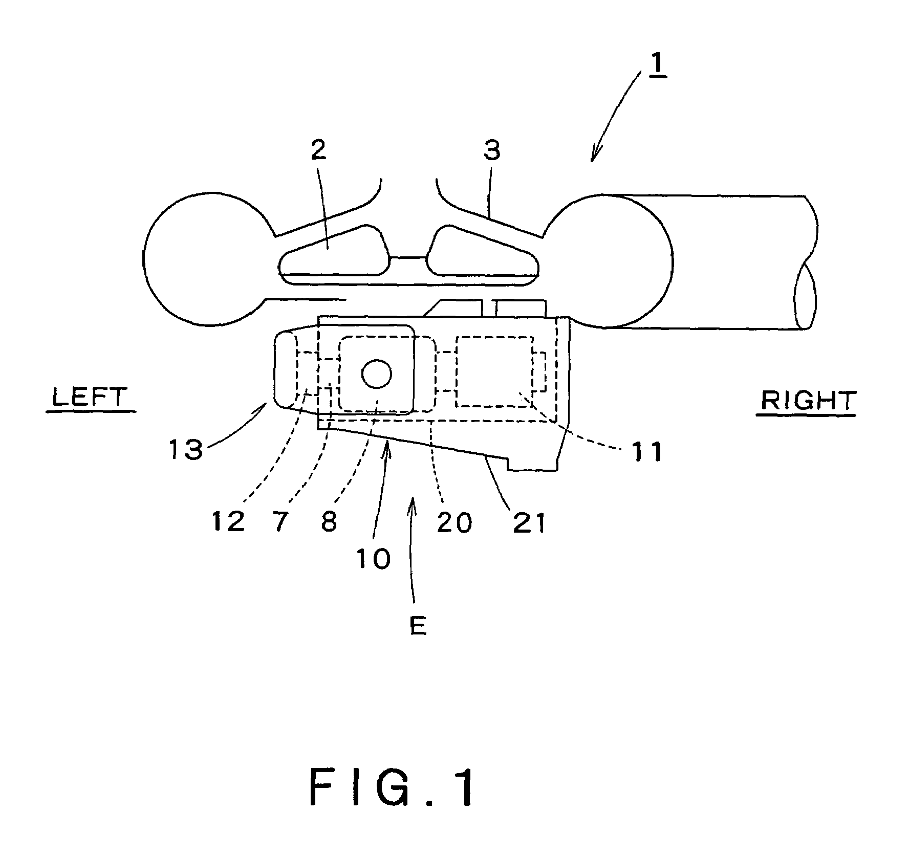
[0040]Referring to FIG. 1, a blower 1 includes a fan 2 and a fan casing 3, and an engine E for driving the fan 2 is joined to a back part of the fan casing 3. The engine E includes an engine body 10 having a cylinder 8. An exhaust muffler 11 is connected to the right side of the cylinder 8, and an intake pipe 7 serving as an insulator is connected to the left side of the cylinder 8. A carburetor 12 is connected to the intake pipe 7. The cylinder 8 and the exhaust muffler 11 of the engine E are covered with an engine cover 20 formed by processing a metal plate. The engine cover 20 is covered with a shroud 21 of a resin. These constructions are basically the same as those shown in FIG. 10.

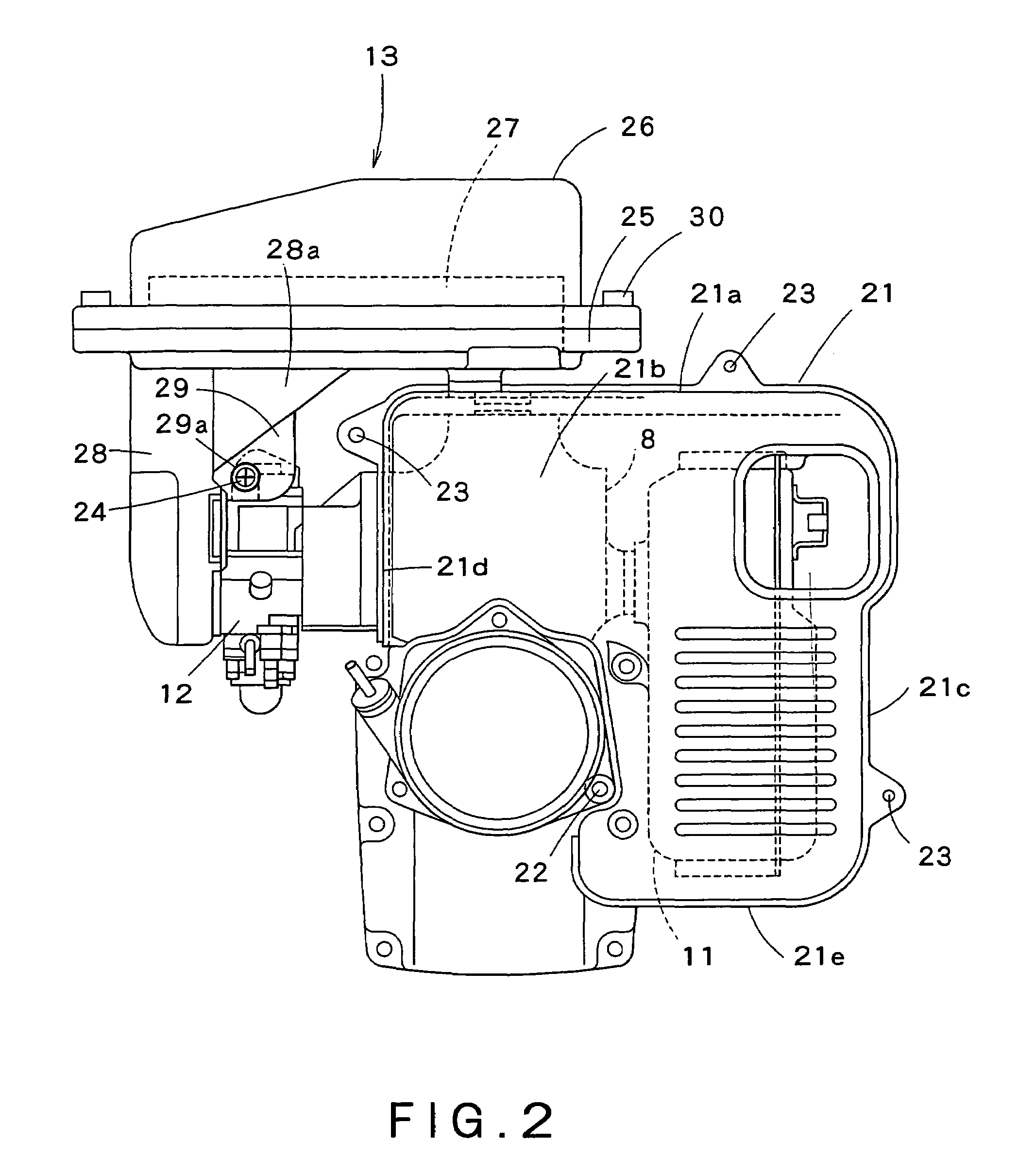
[0041]Referring to FIG. 2 showing the engine E in a rear view, the shroud 21 has ...


PUM

PropertyMeasurementUnit
flexibleaaaaaaaaaa
widthaaaaaaaaaa
strengthaaaaaaaaaa

Abstract

An air cleaner for a portable engine, includes an air cleaner case attached to an upper part of an engine body of the engine. Preferably, the air cleaner case is supported on an upper wall of a shroud covering the engine. Preferably, the air cleaner case is formed integrally with the shroud. Preferably, the air cleaner further includes an air intake structure divided into a plurality of intake passages having inlets displaced relative to each other with respect to an air flow direction in which an intake air flows.

Description

BACKGROUND OF THE INVENTION[0001]1. Field of the Invention[0002]The present invention relates to an air cleaner for a portable engine and, more particularly, to an air cleaner suitable for a portable engine for driving a backpack blower, a backpack power applicator or a hand held bush cutter.[0003]2. Description of the Related Art[0004]FIG. 10 shows a known portable engine E disclosed in JP-A No. 2002-303148 by way of example. This engine is used for driving a backpack blower A as shown in FIG. 9. The backpack blower A includes an engine E, a blower 1, a back frame 15 holding the engine E and the blower 1, a flexible pipe 16 connected to the discharge pipe of the blower 1, a duct 17, and a nozzle 18. An operator supports the back frame 15 holding the engine E and the blower 1 on the operator's shoulders by straps 19 connected to the back frame 15. Air is blown through the nozzle 18 to blow and collect dead leaves M and trash.[0005]Referring to FIG. 10, an exhaust muffler 11 is joine...

Claims


Application Information

Patent Timeline
Patent Type & Authority Patents(United States)
IPC IPC(8): A47L5/00A47L9/00F02B63/00F02B63/02F02M35/024F02M35/04F02M35/10F02M35/12F02M35/16
CPCF02M35/024F02M35/04F02B63/02Y10S55/03Y10T74/2063Y10T74/20606Y10T74/20582
Inventor YUASA, TSUNEYOSHIKOBAYASHI, MASANORI
Owner KAWASAKI HEAVY IND LTD
Why Eureka
Try Eureka