Portable engine-driven centrifugal pump

An engine-driven, centrifugal water pump technology, applied in engine components, engine cooling, machine/engine, etc., can solve problems such as damage to the sealing effect of piston rings, compression ratio, no interface for driving equipment cooling, and more carbon deposits in the engine. The effect of reducing the operation steps and technical difficulty, being easy to carry and transporting, and reducing the weight of the pump body

Active Publication Date: 2015-07-01
浙江东海瑞普科技有限公司
View PDF9 Cites 2 Cited by
  • Summary
  • Abstract
  • Description
  • Claims
  • Application Information

AI Technical Summary

Problems solved by technology

The cooling temperature of the forced air-cooled engine is too low when used in cold conditions, and the engine cannot reach the normal temperature range, resulting in a decrease in fuel gasification efficiency and combustion efficiency, and a decrease in power at the same time, which will cause excessive carbon deposits in the engine and damage the piston. Ring sealing effect and reasonable compression ratio
It is necessary to increase the number of manual maintenance, otherwise the performance of the machine will be reduced or the machine will be damaged. In the case of hot weather, there will be insufficient heat dissipation. If the temperature is too high, the power will drop rapidly and the failure will occur. Therefore, the fan that rotates synchronously with the crankshaft cannot be guaranteed. The engine gets the best working temperature in severe cold and hot weather
Traditional centrifugal water pumps have water inlets, water outlets, etc., and there is no interface to provide cooling for the driving equipment

Method used


Image

  • Portable engine-driven centrifugal pump
  • Portable engine-driven centrifugal pump
  • Portable engine-driven centrifugal pump

Examples


Embodiment Construction

[0017] The present invention will be described in detail below with reference to the embodiments and accompanying drawings. The protection scope of the present invention is not limited to the embodiments, and any changes made by those skilled in the art within the scope defined in the claims also belong to the protection scope of the present invention.

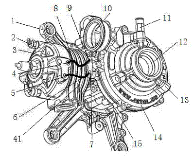
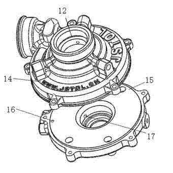
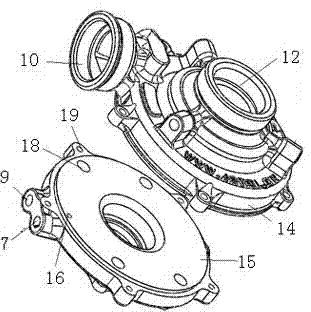
[0018] The portable engine-driven centrifugal water pump of the present invention, as figure 1 , figure 2 , image 3 and Figure 5 Shown, comprise cylinder, water pump and muffler 29. Water pump is provided with pump inlet 10, pump outlet 12, pump cover 14 and pump housing 15, and cylinder comprises cylinder head 3 and cylinder housing 41, and cylinder housing and pump housing cooperate to install, and muffler 29 is connected with the exhaust port of cylinder. A cylinder cooling water channel is arranged inside the cylinder head, and a cooling water inlet 5 and a return water outlet 4 are arranged outside the cylinder hea...


PUM


Abstract

The invention relates to a portable engine-driven centrifugal pump. The pump comprises a cylinder, a water pump and a silencer. A cylinder body of the cylinder and a pump body of the water pump are installed in a fitted mode, and the silencer is connected with an exhaust port of the cylinder. A cylinder cooling water channel is arranged inside a cylinder head, and a cooling water inlet and a return water outlet are formed in the outside of the cylinder head. A return water inlet and a cooling water outlet are formed in the pump body. The return water outlet is connected with the return water inlet through a cooling water return pipe, and the cooling water outlet is connected to the cooling water inlet through a cooling water feed pipe. A pressure switch is arranged on the cylinder head, and the pressure switch is communicated with the cylinder cooling water channel of the cylinder. A water diversion outlet and a negative pressure connecting port are formed in the centrifugal pump, the water diversion outlet is connected with a water and air inlet of a water diversion device through a water pipe, and the negative pressure connecting port is connected with a negative pressure port of the water diversion device through a water pipe. According to the portable engine-driven centrifugal pump, the cooling water channel is utilized to achieve automatic cooling for an engine, and it is facilitated to reduce the energy consumption. The water diversion device is adopted so that the automatic water diversion can be achieved, the operating steps are simplified, the technical difficulty is reduced, and it is guaranteed that the pump can be used successfully under emergency circumstances.

Description

technical field [0001] The invention belongs to the technical field of liquid conveying equipment, and relates to a portable engine-driven centrifugal water pump. Background technique [0002] Existing portable engine-driven centrifugal water pumps all adopt forced air cooling to cool down the engine to ensure that the engine works within a reasonable temperature range. The fan is directly driven by the crankshaft, and the air is guided to the cylinder and cylinder head through the air guide cover to complete the heat dissipation. The fan rotation of this heat dissipation method needs to consume the power of the engine to obtain it. The engine also needs to arrange larger heat sinks to increase the heat dissipation area, resulting in larger volume and increased weight. The cooling temperature of the forced air-cooled engine is too low when used in cold conditions, and the engine cannot reach the normal temperature range, resulting in a decrease in fuel gasification efficien...

Claims


Application Information

Patent Timeline
Patent Type & Authority Applications(China)
IPC IPC(8): F04D13/02F02B63/06F01P5/10F01N1/08
CPCF01N1/089F01P5/10F02B63/06F02F1/40F04D13/02F04D29/426
Inventor 冯长捷刘晓广
Owner 浙江东海瑞普科技有限公司
Why Eureka
Try Eureka