Exhaust gas purifying equipment for a diesel engine

a technology for exhaust gas purification and diesel engines, which is applied in the direction of machines/engines, electric control, separation processes, etc., can solve the problems of deterioration of filter durability, difficult to secure the durability of filters, and inability to be widely adopted

Active Publication Date: 2008-05-13
ISUZU MOTORS LTD
View PDF12 Cites 23 Cited by
  • Summary
  • Abstract
  • Description
  • Claims
  • Application Information

AI Technical Summary

Benefits of technology

[0027]According to the exhaust gas purifying equipment for a diesel engine based on the present invention, it became possible to collect PM and regenerate continuously the DPF without lowering, by the atmosphere and the like, the exhaust temperature raised by the exhaust temperature raising means, as the exhaust temperature is raised

Problems solved by technology

Moreover, securing the durability of the filter becomes problematic, as the temperature becomes high during the PM burning.
For these reasons, this method has not come to be widely adopted.
In a state such as where a great quantity of PM is accumulated, if PM burning occurs, the burning progresses in a moment to causing considerable deterioration of filter durability or other problems.
, therefore NO is not sufficiently oxidized to NO2 in the oxidation catalyst. H
ence the PM collected by the DPF is does not burn sufficiently and consequently the PM collection efficiency of the filter also lowers. A
s a result, the filter itself becomes clogged early, or causing other unf

Method used


Image

  • Exhaust gas purifying equipment for a diesel engine
  • Exhaust gas purifying equipment for a diesel engine
  • Exhaust gas purifying equipment for a diesel engine

Examples


Embodiment Construction

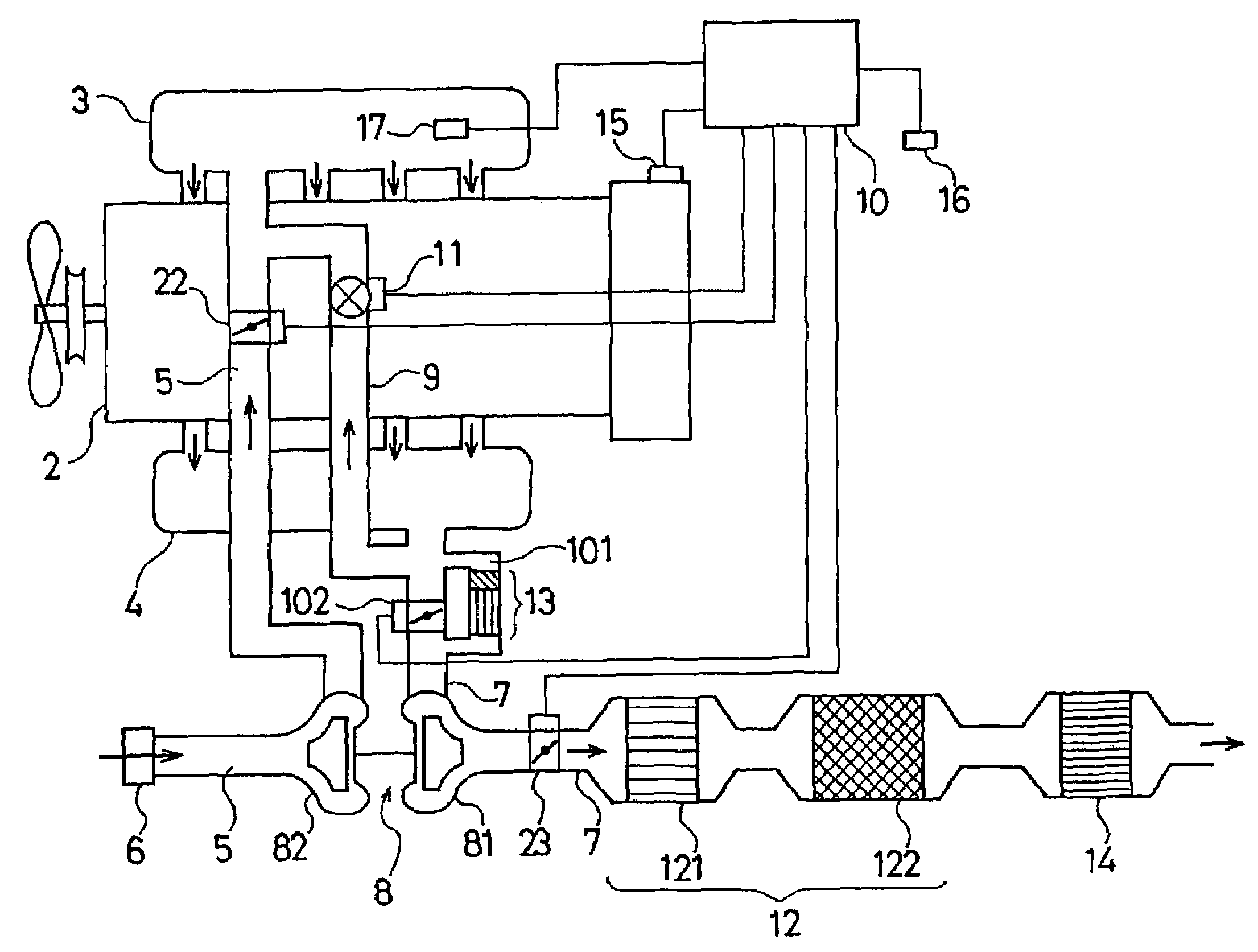
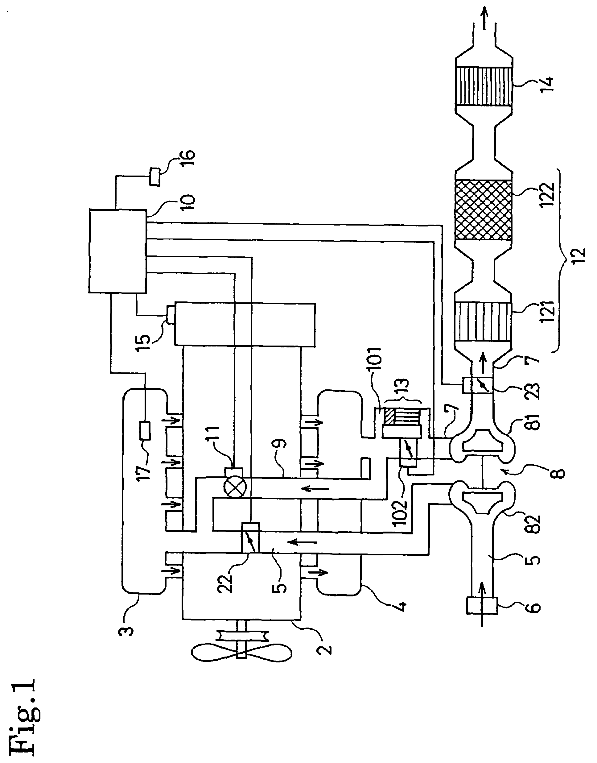
[0044]Now, a preferable embodiment of the present invention shall be described below using drawings. FIG. 1 is a schematic composition diagram showing an embodiment of an exhaust gas purifying equipment for a diesel engine composed according to the present invention. It should be appreciated that, in the embodiment shown in FIG. 1, component members same as those in the conventional exhaust gas purifying equipment shown in the aforementioned FIG. 12 are assigned with the identical numbers and detailed description thereof shall be omitted.

[0045]The exhaust gas purifying equipment for a diesel engine in the embodiment shown in FIG. 1 is provided with an intake valve (intake shutter) 22 disposed at the upstream of the connection of an EGR passage in the intake pipe 5 constituting a part of the intake passage for limiting the intake air quantity. This intake valve 22 is regularly kept full open. Besides, an exhaust valve (exhaust shutter) 23 for limiting a discharge of an exhaust gas is...


PUM

PropertyMeasurementUnit
Fractionaaaaaaaaaa
Fractionaaaaaaaaaa
Angleaaaaaaaaaa

Abstract

An exhaust gas purifying equipment for a diesel engine having a first continuous regeneration type DPF (12) in an exhaust passage (7) of an engine (2), a second continuous regeneration type DPF (13) in a bypass passage (101), a switching valve (102) for switching the flow path of an exhaust gas, an exhaust temperature raising means, an exhaust temperature area detector, and a controller controlling the exhaust temperature raising means and the switching valve (102), wherein the controller operates the exhaust temperature raising means and at the same time executes the post-injection, and, furthermore, controls the switching valve (102) so that the exhaust gas passes through the second continuous regeneration type DPF (13), in the case where the exhaust temperature area of an engine (2) detected by the exhaust temperature area detector is in an extremely low temperature area (Z2) of which the exhaust temperature is lower than that of a predetermined temperature area.
Thereby, even under an environment such as a very cold land, the PM collected by the DPF can be made burn steadily and continuously over the whole operating range of an in-vehicle diesel engine.

Description

BACKGROUND OF THE INVENTION[0001]The present invention concerns an exhaust gas purifying equipment for removing a particulate in the exhaust gas of diesel engines.[0002]Regulations on the exhaust gas of recent internal combustion engines, especially diesel engines are further reinforced year by year, and, in particular, it has become urgent to reduce particulate matter (PM, hereinafter) containing mainly carbon. The diesel particulate filter (DPF, hereinafter) is known as a equipment for removing this PM from the exhaust. In addition, the movement to enforce equipping a vehicle having a diesel engine with a DPF is becoming a reality.[0003]However, as the collected PM would accumulate in the DPF to be provided on a vehicle having a diesel engine due to a repeated driving of the engine, it is necessary to regenerate the DPF by burning the collected PM. As this regeneration means, methods for burning PM by heating with an electric heater or a burner and so on are known.[0004]In the cas...

Claims


Application Information

Patent Timeline
IPC IPC(8): F01N3/00F01N3/02F02D9/02F01N3/023F01N3/025F01N3/029F01N3/031F01N3/20F01N3/36F01N13/02F02B37/00F02D9/04F02D13/02F02D41/02F02D41/04F02D41/38F02D41/40F02D45/00F02M25/07
CPCF01N3/0231F01N13/009F01N3/031F01N3/2053F02D13/02F02D41/024F02D41/405F02M25/0713F02M25/0752F01N13/0097F01N3/0235F01N2250/02F01N2340/06F01N2410/02F01N2430/10F02B37/00F02D9/04F02D2013/0296F02D2200/0414F02D2200/501F02M25/0704F02M25/0772Y02T10/44Y02T10/18Y02T10/26F02M26/02F02M26/10F02M26/01F02M26/53Y02A50/20Y02T10/12Y02T10/40
Inventor MINAMI, TOSHITAKA
Owner ISUZU MOTORS LTD
Why Eureka
Try Eureka