Method and device for laying of elongated winding material

a technology of winding material and elongated spool, which is applied in the direction of printing, instruments, transportation and packaging, etc., can solve the problems of affecting the durability of plastic spools, affecting the axial pressure of the spool flange, and deformation of elastically, so as to reduce the winding speed and reduce the rotational speed , the effect of uniform winding pattern

Active Publication Date: 2008-05-13
MASCHFAB NIEHOFF GMBH & CO KG
View PDF9 Cites 20 Cited by
  • Summary
  • Abstract
  • Description
  • Claims
  • Application Information

AI Technical Summary

Benefits of technology

[0020]The method according to the present invention makes it possible to achieve the best possible winding pattern, without hills and valleys, on arbitrary spools while simultaneously avoiding an elastic deformation of the spool flange, and has significant advantages relative to the methods known from the prior art.
[0027]In the method according to the present invention, the sensor unit is also used for the recognition of the spool flange. Here, preferably each time there is a laying stroke the position of the flange is determined on the basis of the measurement value changes of the sensor unit, and the values are used for the subsequent controlling of the change of direction. Preferably, the method according to the present invention automatically provides the necessary tracking of the reverse points. This permanent correction of the reverse points prevents the undesired formation of hills or valleys in the winding material at the flange. In addition, there results a very high degree of user-friendliness, because no correction of the reverse points is required on the part of the person operating the equipment. In addition, this function is independent of the winding laying pattern used.
[0029]Through the determination of the spool or winding material angle and the automatic flange recognition, it is possible to use this method independent of the construction of the spool. The determined angle is taken into account in the controlling of the automatic laying, or in the flange recognition. Thus, for example an oblique winding as described in EP 0 334 211 B1, as well as laying on cylindrical, conical, and biconical spools, can be controlled. Here, after the acquisition of valleys, the winding speed can be reduced by reducing the rotational speed of the spool or of the flyer, and / or the axial speed of the laying unit can be throttled. Given an acquisition of hills, in order to restore a uniform winding pattern the winding speed can be increased, and / or what are known as shift steps of the laying unit can be executed in the direction of the spool axis.

Problems solved by technology

Here, when the change of direction of the laying unit takes place too late, there results an axial pressure on the spool flange, which deforms elastically as a result, in particular in the case of plastic spools.
On the one hand, this has a disadvantageous effect on the durability of the plastic spools, and on the other hand the elastic reset forces of the flange cause problems in the later unwinding of the elongated winding material from the spool.
In this way, at the beginning of each winding layer there arise intermediate spaces, called “valleys,” into which the windings of the layer situated thereabove are wound, which can cause difficulties in the later unwinding of the winding material.
As a result of these phenomena, non-uniform layers are formed, especially in the edge areas of the winding.
The formation of hills and valleys is also caused by an improper setting of the laying width of the winding material, or, as mentioned, by a deformation of the spool flange.
In addition to the non-uniform and therefore unsatisfactory use of the winding space caused by the formation of hills and valleys, the winding material is also excessively stressed, and can thus be damaged.
These methods supply relatively imprecise signals on the basis of which no conclusion can be drawn concerning the amplitudes of the hills and valleys.
A disadvantage of both these systems is the indirect detection of the winding quality on the basis of parameters such as rotational speed, wire feed length, or laying speed.
A laying width adjustment cannot be carried out until deviations of these parameters occur or the spool flange is already deformed, i.e., until a “significantly” non-uniform winding pattern has already occurred.
A disadvantage of this system is that the laser distance sensor acquires only the distance from the deflecting roller to the winding material.
It is true that in this way a signal can be derived for accelerating or retarding the shifting unit, but an exact calculation of the speed of the laying device required for the compensation of the non-uniform surface is not possible in the manner described.
This results in an elastic deformation of the spool flange and the formation of a hill leaning on the flange.
The use of the known method for improving the winding pattern in the laying of winding material is also made more difficult if the supply of energy and the exchange of signals, such as in the case of stranding machines, is possible only via rotating components.

Method used


Image

  • Method and device for laying of elongated winding material
  • Method and device for laying of elongated winding material
  • Method and device for laying of elongated winding material

Examples


Embodiment Construction

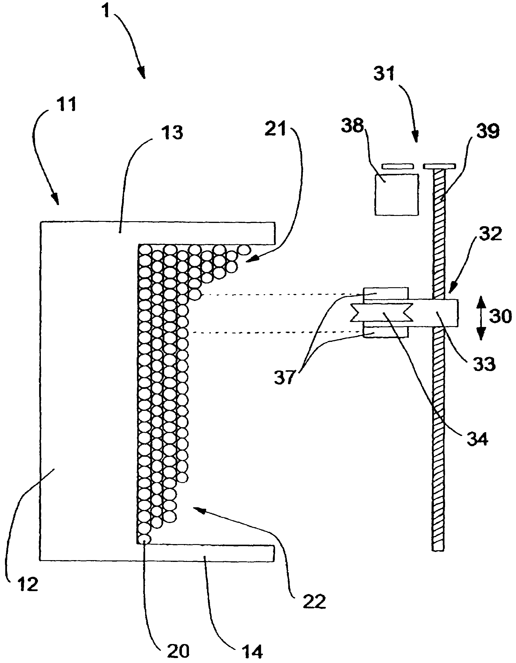
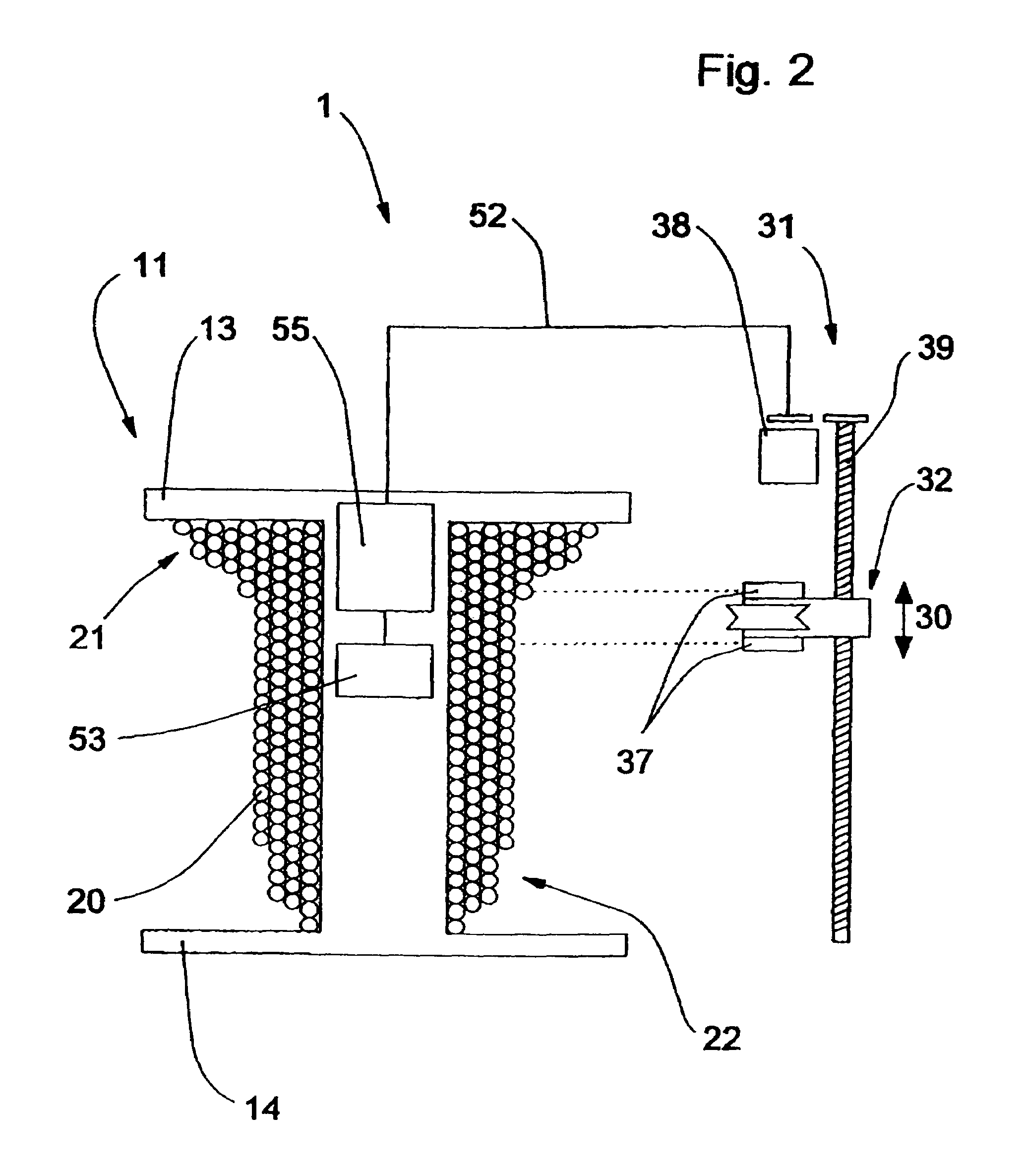
[0034]FIG. 1 shows a schematic cross-section through a winding device 1 for carrying out the method according to the present invention. In the Figure, at the left the right half of a winding spool 11 is shown, made up of spool core 12 and the two flanges 13 and 14, in section. The object of the method according to the present invention is to wind spool core 12 with elongated winding material 20 as uniformly as possible, in order to make optimal use of the winding volume of winding spool 11. In the Figure, the depicted examples of undesirable valleys are designated 22 and the hills are designated 21.

[0035]Laying device 31 is shown at the right in FIG. 1. Laying unit 32 is mounted on a spindle axle 39. A rotational movement of spindle axle 39 clockwise or counterclockwise effects a movement of laying unit 32 in a direction essentially parallel to the spool axis, indicated by double arrow 30. Spindle axle 39 is driven by motor 38. Laying unit 32 has a carriage 33 on which deflecting ro...


PUM


Abstract

A method for laying elongated winding material, such as for example wire, insulated or non-insulated strands, glass fibers, and the like, in which the strand-type material is wound in layers onto rotationally symmetrically shaped winding spools, the winding material being guided to a winding spool via a deflecting roller for the laying, and for the distribution on the winding spool the deflecting roller is moved essentially parallel to the axial direction, a sensor unit acquiring the position of the spool flange as well as the winding diameter of the winding material, and control signals for the movement of the deflecting roller being derived from the measurement values of the sensor unit.

Description

BACKGROUND[0001]The present invention relates to a method for laying elongated winding material, such as for example wire, insulated or non-insulated strands, glass fibers, and the like, as well as a device for executing the method.[0002]In known winding methods, a strand-type material is for example attached to a rotating spool and is thus wound onto the core of the spool. In order to achieve a layered winding, i.e. to lay the wire windings next one another on the spool, a deflection roller that guides the winding material to the spool moves essentially parallel to the axial direction of the rotating spool. It is also known to situate the spool in stationary fashion and to cause a flyer that also moves axially to move around the spool, said flyer laying the winding material around the spool in layers.[0003]In order to obtain a particular type of winding (layer on layer), it is also known to cause the axially displaceable laying unit on which the deflecting roller is situated to tra...

Claims


Application Information

Patent Timeline
Patent Type & Authority Patents(United States)
IPC IPC(8): B65H57/28
CPCB65H54/286B65H54/2878D07B2207/4036
Inventor LAMMERMANN, HELMUTBADER, RUDOLFBECK, WOLFGANGENZENSBERGER, BERNHARD
Owner MASCHFAB NIEHOFF GMBH & CO KG
Why Eureka
Try Eureka