Check patentability & draft patents in minutes with Patsnap Eureka AI!

Model railroad switch machine

a switch machine and model technology, applied in the direction of toys, ways, constructions, etc., can solve the problems of adding a level of complexity, not very realistic, and changing the position of the switch typically takes several seconds

Inactive Publication Date: 2008-05-13
ZANDER DENNIS R
View PDF16 Cites 0 Cited by
  • Summary
  • Abstract
  • Description
  • Claims
  • Application Information

AI Technical Summary

Benefits of technology

"The invention is a switch machine for a model railroad layout that can move a switch actuator between two positions at slow and fast speeds to mimic the operation of a real railroad switch. The machine includes a controller that can adjust the power and speed of the motor to control the switch actuator. The machine is enclosed in a housing with a push button for easy operation. The machine can also be addressable and store route information to set the switch to a specific position. The technical effects of this invention include the ability to control the operation of a railroad switch with a model switch machine that can mimic the real thing."

Problems solved by technology

One problem with solenoid actuators is that they produce a snap action that is effective for moving the switch but which is not very realistic.
Switch machines for actual locomotives use relatively large, slow moving motors and changing the position of a switch typically takes several seconds.
While these have the ability to provide a realistic switching speed, they add a level of complexity.
This adds complexity and cost to the controller and multiplies the number of wires that must be run to the switch machine.
Such light signals are important because the position of the switch is often difficult to see directly and a miss positioned switch could cause a derailment.
While signal lights are known for use in model railroad switching machines, a problem not so far addressed is the problem of synchronizing the lights with the position of the switch especially when the model railroad switch machine is responsive to a switching signal to switch from whatever state it is presently in to the other state.

Method used


Image

  • Model railroad switch machine
  • Model railroad switch machine
  • Model railroad switch machine

Examples


Embodiment Construction

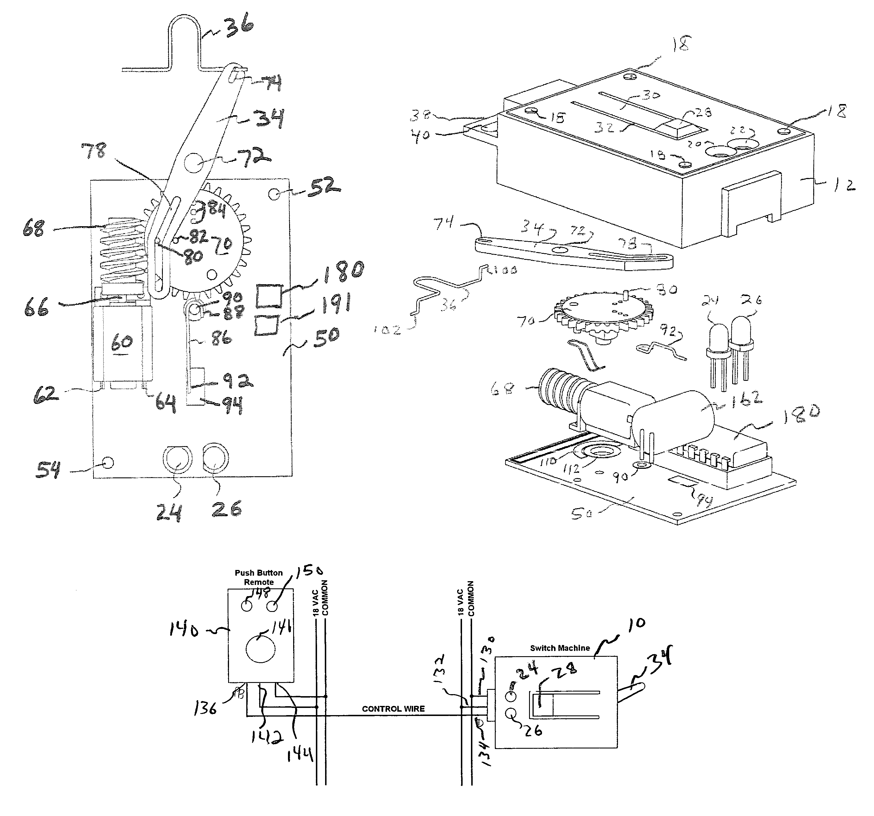
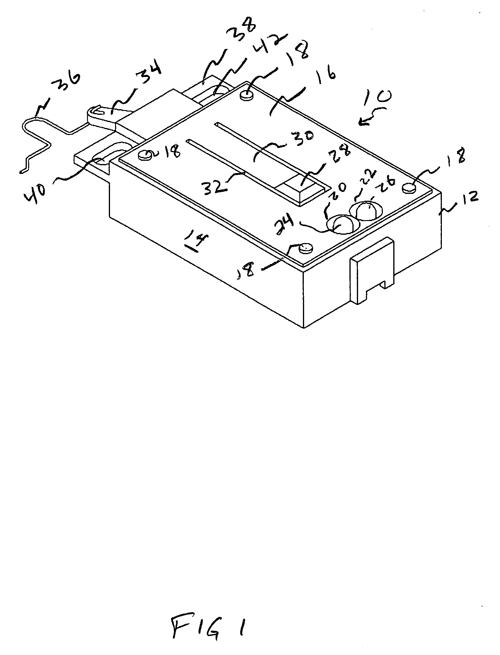
[0041]Referring now to FIG. 1, the switch machine indicated generally at 10 is enclosed within a housing 12 preferably made from plastics or similar materials which includes a base 14 and a cover 16. The cover is attached to the base by fasteners 18 located at the corners of the cover 16. The cover is provided with apertures 20 and 22 for receiving signal lamps 24 and 26.

[0042]A push button 28 is formed in the cover 16 at the end of a cantilevered arm 30 formed in the cover plate 16 by a peripheral slot 32.

[0043]A switch actuator portion of the switch machine includes a pivotally mounted lever 34 extending from an end of housing 12 and connected to a linkage 36 which attaches the arm to a switch.

[0044]A mounting flange 38 extends from one end of the housing 12 and includes elongated apertures 40 and 42 for mounting the switch machine to a support for a model railroad layout.

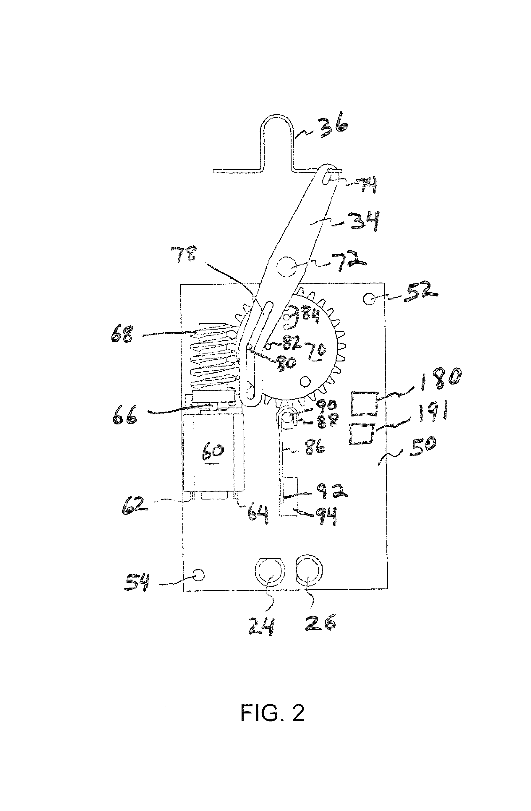
[0045]FIG. 2 is a slightly simplified top plan view of the interior of the switch machine 10 with the switch a...


PUM


Abstract

A switch machine for a model railroad layout includes a unidirectional motor, a switch actuator coupled to the motor and movable between two switch positions by rotation of the motor, a sensor coupled to the switch actuator for sensing the position of the switch actuator, and a controller connected to the motor and the sensor and having a power input and at least a single wire control input, the controller responsive to a first control signal to activate the motor to move the switch actuator from a first position to a second position at a slow speed simulating an actual railroad switch, and responsive to a second control signal to move the switch actuator from a first position to a second position at a fast speed to avoid a derailment.

Description

CROSS-REFERENCE TO RELATED APPLICATIONS[0001]Not ApplicableSTATEMENT REGARDING FEDERALLY SPONSORED RESEARCH OR DEVELOPMENT[0002]Not ApplicableREFERENCE TO A “SEQUENCE LISTING”[0003]Not applicable.BACKGROUND OF THE INVENTION[0004]1. Field of the Invention[0005]This invention relates in general to model railroad switch machines and more particularly to a model railroad switch machine having a single wire control input, user programmable synchronization of indicator lights, realistic slow speed switching action simulating the operation of full size railroad switches and self calibration for enhancing realism as switch mechanical resistance and voltage changes are encountered.[0006]2. Description of Related Art[0007]Known switch machines or switch actuators for model railroad applications take a variety of forms. Solenoids are commonly used to actuate the switches because they are small and efficient and can provide relatively high power. One problem with solenoid actuators is that they...

Claims


Application Information

Patent Timeline
Patent Type & Authority Patents(United States)
IPC IPC(8): A63H19/00
CPCA63H19/32
Inventor ZANDER, DENNIS R.
Owner ZANDER DENNIS R
Features
  • R&D
  • Intellectual Property
  • Life Sciences
  • Materials
  • Tech Scout
  • Unparalleled Data Quality
  • Higher Quality Content
  • 60% Fewer Hallucinations
Learn More