Work transfer device and method of transferring work

a work transfer and work technology, applied in the direction of furniture parts, tableware, hoisting equipment, etc., can solve the problems of letting work fall along with the frame, affecting work safety, and affecting work safety, so as to prevent the frame from falling and transfer work safely.

Inactive Publication Date: 2008-05-13
TOKYO SEIMITSU
View PDF7 Cites 5 Cited by
  • Summary
  • Abstract
  • Description
  • Claims
  • Application Information

AI Technical Summary

Benefits of technology

[0010]As a result of this, in a case where the adsorption of the frame becomes impossible during work transfer because of a power failure or due to troubles in valves and the like, the frame released from the adsorption is received by the frame clamps present in the lower portion of the frame and the work does not fall. Therefore, it is possible to safely perform the transfer of the work.
[0014]As a result of this, the frame clamps do not hinder the adsorption of the frame by the adsorption part. Even when the adsorption of the frame does not work any more during transfer because of a power failure or due to troubles in valves and the like, the frame clamps do not move until a driving source of air and the like for moving the frame clamps is newly supplied. Therefore, the frame clamps do not let the work to fall.
[0017]As a result of this, even when the adsorption of the frame does not work any more during work transfer because of a power failure or due to troubles in valves and the like and the frame falls, the frame is received by the frame clamps and hence the fall of the frame is prevented.
[0018]As described above, according to a work transfer device and a method of transferring work of the present invention, even when the adsorption of the frame does not work any more because of a power failure or due to troubles in parts and the like, it becomes possible to safely transfer work without letting the work to fall.

Problems solved by technology

However, in such adsorption methods, there are cases where it becomes impossible to maintain a vacuum state during a power failure or due to troubles in valves connected in intermediate portions and the like, and there is a danger that work is let to fall along with the frame and be broken.

Method used


Image

  • Work transfer device and method of transferring work
  • Work transfer device and method of transferring work
  • Work transfer device and method of transferring work

Examples


Embodiment Construction

[0027]Preferred embodiments of a work transfer device and a method of transferring work of the present invention will be described in detail with reference to the accompanying drawings.

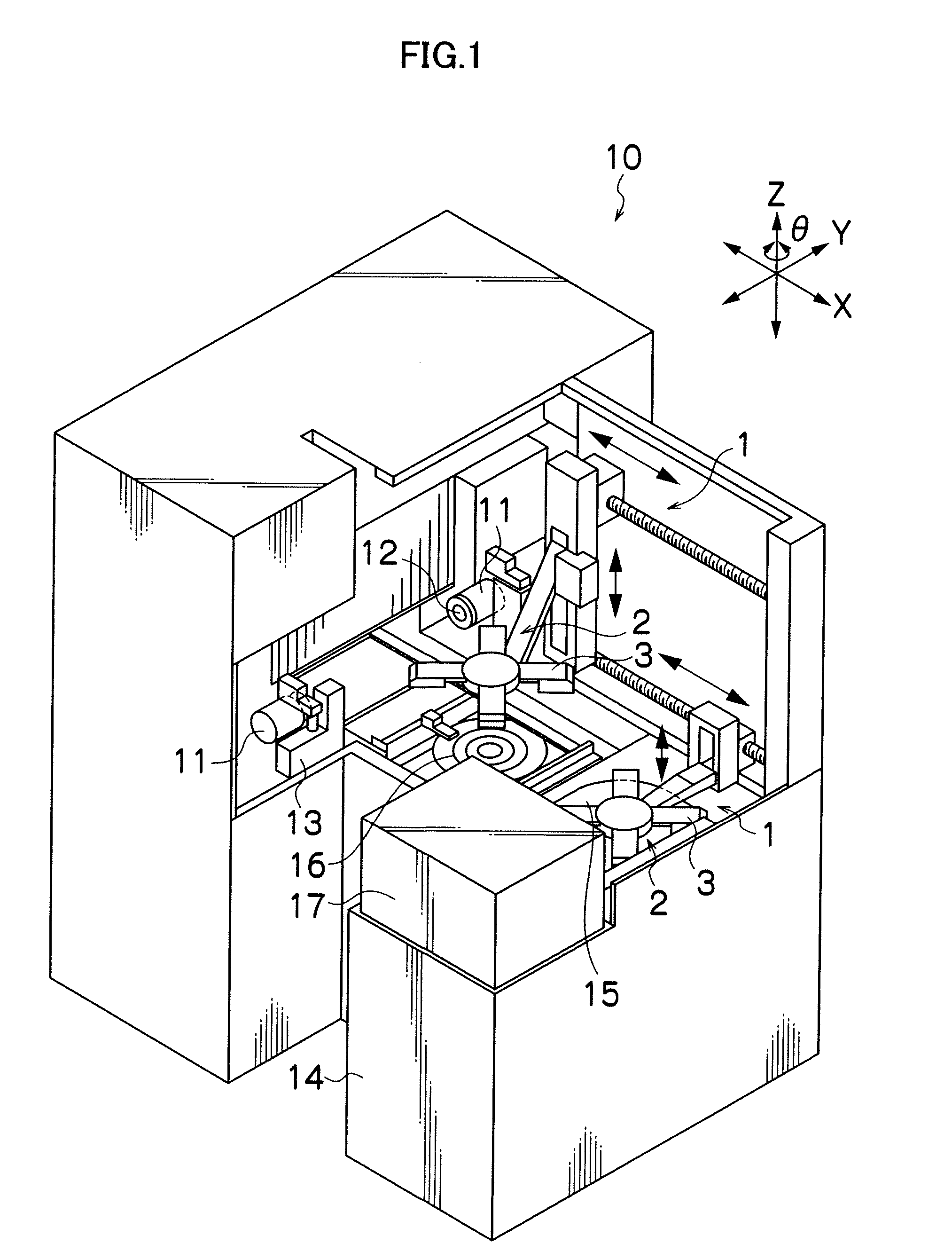
[0028]First, a description will be given of the construction of a wafer polishing machine in which a work transfer device related to the present invention is incorporated. FIG. 1 is a general perspective view of the wafer polishing machine.

[0029]A dicing machine 10 is equipped with high-frequency motor incorporated spindles 11, 11 which are disposed opposed to each other in order to perform the working of work, and to a leading end of which a blade 12 and an unillustrated wheel cover are attached, a microscope 13 attached near the spindle 11 to observe the work, and a worktable 16 which adsorbs and holds the work.

[0030]In addition, the dicing machine 10 is equipped with work transfer devices 1, 1 which perform the transfer of work, a spinner 15 which performs the spin cleaning of worked work W, an ele...


PUM


Abstract

Provided are a work transfer device and a method of transferring work which are capable of safely transferring work without letting the work to fall even when poor adhesion of a frame occurs due to troubles. By providing an adsorption part which adsorbs a frame, and a plurality of frame clamps which move to near a bottom surface of the frame when the frame has been adsorbed and transferred by the adsorption part, and which retract from near the bottom surface of the frame when the transfer of the frame has been finished and the adsorption of the frame has been finished.

Description

BACKGROUND OF THE INVENTION[0001]1. Field of the Invention[0002]The present invention relates to a work transfer device which transfers work, such as semiconductor devices and electronic parts, and a method of transferring work.[0003]2. Description of the Related Art[0004]The rear surface of work which is a plate-work object on the surface of which a semiconductor device, an electronic part and the like are formed, is as shown in FIG. 7 stuck on a dicing tape T having an adhesive material on the top surface thereof. The work W stuck on the dicing tape T is mounted on a frame F via the dicing tape T. The work W mounted on the frame F is transferred in this state within a dicing machine or a die bonding machine or between these machines and the like, and various kinds of working are performed by each of the machines. In transferring the work W, it is general practice to perform the transfer by vacuum adsorbing the frame F (refer to Japanese Patent Application Laid-Open No. 7-169716, f...

Claims


Application Information

Patent Timeline
Patent Type & Authority Patents(United States)
IPC IPC(8): B25J15/06
CPCH01L21/6838H01L21/68707Y10S294/907H01L21/67H01L21/68
Inventor IMAI, SHINOBU
Owner TOKYO SEIMITSU
Why Eureka
Try Eureka