Magnetic resonance imaging method and apparatus

a magnetic resonance imaging and magnetic field technology, applied in the field of magnetic resonance imaging, can solve the problems of extending the computation time considerably, and achieve the effects of fast imaging, shortening the imaging time, and fast computation

Active Publication Date: 2008-05-13
FUJIFILM HEALTHCARE CORP
View PDF8 Cites 19 Cited by
  • Summary
  • Abstract
  • Description
  • Claims
  • Application Information

AI Technical Summary

Benefits of technology

[0007]The invention therefore has an object to perform fast imaging by shortening an imaging time from the signal measurement to the image display in the PROPELLER sampling method. In particular, the invention has an object to enable fast computation by reducing a computation volume needed for image reconstruction by shortening an imaging time through application of the parallel imaging method.

Problems solved by technology

However, when the parallel imaging method is applied to the PROPELLER sampling method as above, it is necessary to remove aliasing artifacts by applying the generalized aliasing artifact development algorithm to the data of the entire k-space that has been measured by skipping, and this need extends a computation time considerably.

Method used


Image

  • Magnetic resonance imaging method and apparatus
  • Magnetic resonance imaging method and apparatus
  • Magnetic resonance imaging method and apparatus

Examples


first embodiment

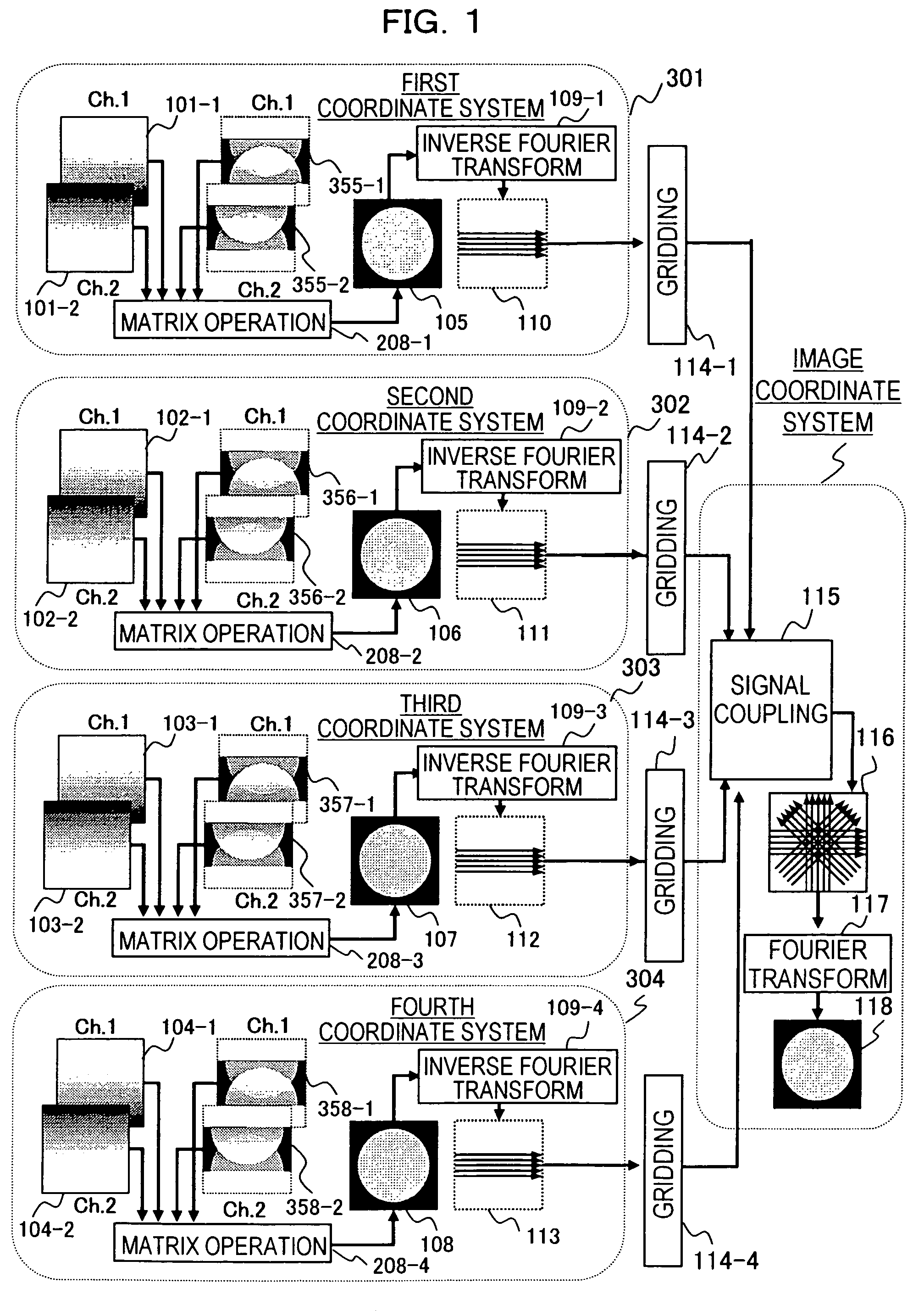
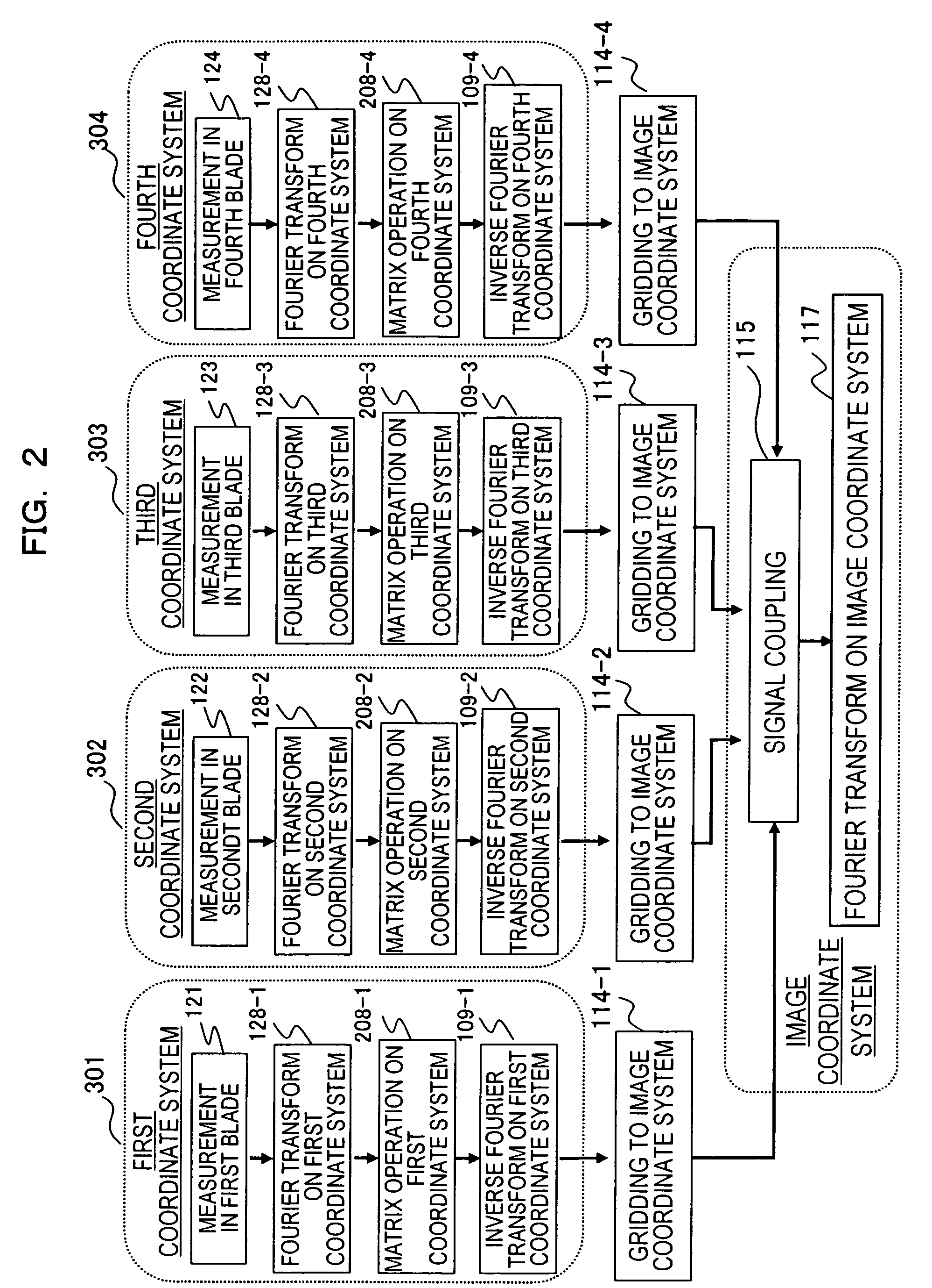
[0076]On the basis of the principles of the PROPELLER MRI method and the parallel MRI method as above, a first embodiment of the invention will now be described with reference to FIG. 1 and FIG. 3.

[0077]For ease of description, the PROPELLER MRI method in a case where measurements are performed using four blades will be described. FIG. 3a shows the PROPELLER MRI method in a normal case where ten echo signals are acquired within each of four blades 301 through 304. In contrast, FIG. 3b shows a case where only half (five) the echo signals are acquired by setting the intensity of the phase encoding gradient magnetic field to be applied within each blade twice as high as that of FIG. 3a. Solid lines in the drawing represent echo signals that will be measured, and dotted lines represent positions of echo signals that will not be measured.

[0078]When measurements are performed in this manner, aliasing artifacts occur in an image. However, because an angle of the k-space differs from blade ...

second embodiment

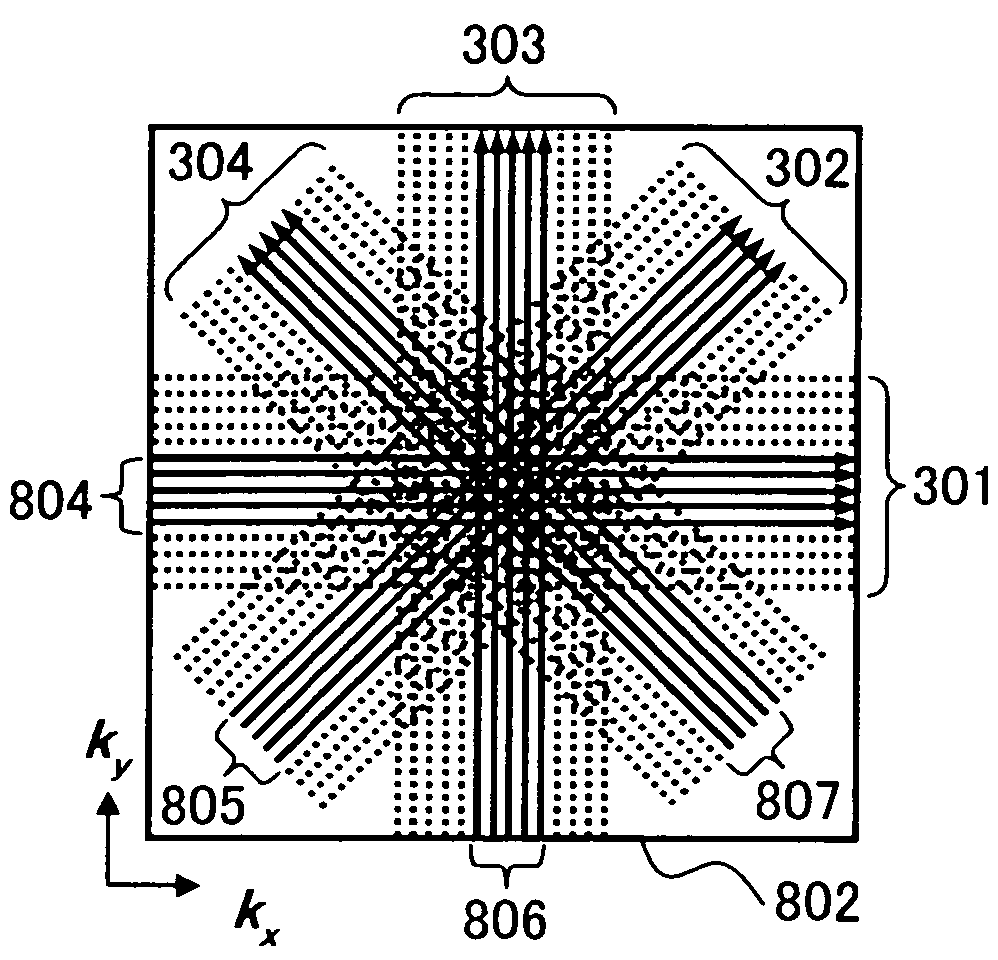
[0087]A second embodiment of the invention will now be described with reference to FIG. 8. For simplicity of description, the PROPELLER MRI method in a case where the number of blades is four will be described. In this embodiment, echo signals are acquired as are shown in FIG. 8a (solid lines represent echo signals that will be measured, and dotted lines represent trajectories of echo signals that will not be measured). A difference from FIG. 3b is the number of and intervals between parallel trajectories within each blade in a k-space 801. In other words, k-spaces within the respective blades 301 through 304 are divided to low spatial frequency regions 804 through 807 and high spatial frequency regions on the outside, and phase encoding steps when acquiring echo signals in the low spatial frequency regions are made smaller (that is, denser) than phase encoding steps in the high spatial frequency regions. Conversely, phase encoding steps when acquiring echo signals in the high spati...

third embodiment

[0101]A third embodiment of the invention will now be described with reference to FIGS. 9 and 10. Because the reconstruction processing in the parallel MRI method is independent for each blade according to the method of the invention, image reconstruction processing for a given blade can be started at a time point at which echo signal data within this blade has been obtained, which enables faster imaging.

[0102]For simplicity of description, the PROPELLER MRI method in a case where measurements are performed using four blades will be described. FIGS. 9 and 10 show cases where the invention is applied to continuous imaging using the PROPELLER MRI method comprising four blades 301 through 304, and the horizontal direction indicates a time course.

[0103]FIG. 9 shows an example of a method of enhancing time resolution of each image by forming an image for each blade. As is shown in FIG. 9, because processing is performed for each of the blades 301 through 304, parallel development process...


PUM


Abstract

In a magnetic resonance imaging apparatus, an RF pulse is applied to a subject placed in a static magnetic field, a plurality of gradient magnetic fields are applied, and induced nuclear magnetic resonance signal (echo signal) is received by means of a RF receiving coil unit composed of two or more RF receiving coils. A parallel MRI method is applied to echo signals acquired by reducing the echoes per blade of a propeller MRI method so as to remove the artifact to produce a reconstructed image. The reconstructed image is subjected to inverse Fourier transform to return it to the echo signals in a measurement space corresponding to the blade. The echo signals are girded in an arbitrarily predetermined coordinate system for image and combined. Such a processing is conducted for the echo signals of all the blades. A final image is reconstructed using the echo signals after the image creation in the coordinate system for image.

Description

TECHNICAL FIELD[0001]The present invention relates to a magnetic resonance imaging (hereinafter, abbreviated as MRI) apparatus used to obtain a tomographic image of a region being examined of a subject with the use of a nuclear magnetic resonance (NMR) phenomenon, and more particularly, to a technique for shortening an imaging time and an image reconstruction time by combining the PROPELLER sampling method and the parallel imaging method that uses plural high-frequency receiver coils.BACKGROUND ART[0002]For an MRI apparatus, the Cartesian sampling method for taking samples along trajectories parallel to the orthogonal coordinate axis of the k-space is often used as a scheme for acquiring echo signals on the k-space needed for image reconstruction. However, a method referred to as non-Cartesian sampling for taking samples along trajectories that are not parallel to the orthogonal coordinate axis of the k-space has been receiving attention in recent years, and one example is the PROPE...

Claims


Application Information

Patent Timeline
Patent Type & Authority Patents(United States)
IPC IPC(8): G01V3/00G01R33/48A61B5/055G01R33/3415G01R33/54G01R33/561
CPCG01R33/4824G01R33/5611
Inventor TAKIZAWA, MASAHIROTAKAHASHI, TETSUHIKOTANIGUCHI, YO
Owner FUJIFILM HEALTHCARE CORP
Why Eureka
Try Eureka