Method and apparatus for graphically defining a video particle explosion effect

a particle explosion and video technology, applied in the field of real-time 3d video effects, can solve the problems of low cost of dve (digital video effects) products, limited creative freedom of editors, and compromise of quality

Inactive Publication Date: 2008-05-13
MATROX
View PDF19 Cites 27 Cited by
  • Summary
  • Abstract
  • Description
  • Claims
  • Application Information

AI Technical Summary

Benefits of technology

[0012]Consequently, it is an object of the present Particle explosion effect invention to provide a real t...

Problems solved by technology

1) Coding and validating every transformation of the effect in the chip is a lengthy process, so typically only a small set of parameters is provided. As a result, the editor has limited creative freedom.
2) To keep the cost of DVE (Digital Video Effects) products as low as possible, manufacturers often use simplified algorithms to minimize the complexity of their chips. Quality is therefore compromised.
3) Particle shapes are simple and hard coded. Users have no possibility of defining their own shapes.
However, the shapes are quite simple (triangles, squares, etc.) and the user does not have the ability to...

Method used


Image

  • Method and apparatus for graphically defining a video particle explosion effect
  • Method and apparatus for graphically defining a video particle explosion effect
  • Method and apparatus for graphically defining a video particle explosion effect

Examples


Embodiment Construction

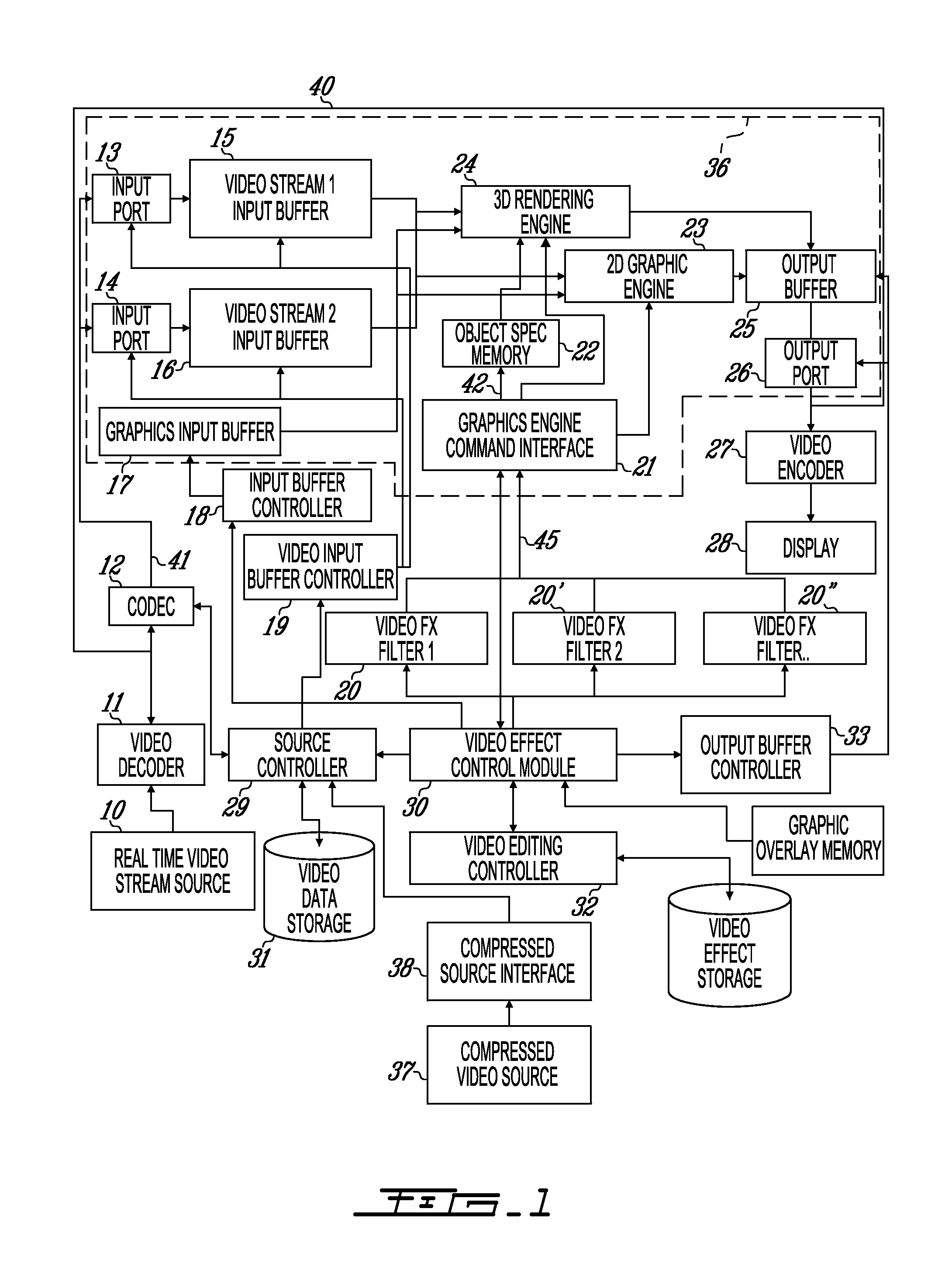
[0031]While illustrated in the block diagrams as ensembles of discrete components communicating with each other via distinct data signal connections, it will be understood by those skilled in the art that the preferred embodiments are provided by a combination of hardware and software components, with some components being implemented by a given function or operation of a hardware or software system, and many of the data paths illustrated being implemented by data communication within a computer application or operating system. The structure illustrated is thus provided for efficiency of teaching the present preferred embodiment.

[0032]The real time capability of this effect is made possible by a Real time video editing system architecture and described in commonly assigned co-pending U.S. patent application Ser. Nos. 09 / 653,701, 09 / 653,703 (now issued as U.S. Pat. No. 6,763,175) and U.S. patent application Ser. No. 09 / 653,704 (now issued as U.S. Pat. No. 6,763,176).

[0033]The Real ti...


PUM


Abstract

A software library using a 3D graphics engine to produce a real time 3D particle explosion effect is provided. The particle explosion effect creation tool allows users to create their own particle explosion effect by defining their own shapes in a graphics image data file and allows to graphically define a plurality of explosion parameters of the video particle explosion effect in the graphics image data file. Particles are driven by a particle system algorithm that is controlled by real-world attributes such as gravity, direction and dispersion. These attributes can be keyframed by the users within a video editing application to produce specific 3D Particle explosion effects such as transitions and filters on video or graphics.

Description

FIELD OF THE INVENTION[0001]The invention relates to a real time 3D video effect. More specifically, it relates to a particle explosion effect.BACKGROUND OF THE INVENTION[0002]The hardware solutions currently proposed on the market for a particle explosion effect are based on dedicated chips that perform fixed functions at a fixed resolution. This approach requires that all effects be programmed in the chip which includes only a limited set of attributes that can be applied by the user. Drawbacks to such an approach include:[0003]1) Coding and validating every transformation of the effect in the chip is a lengthy process, so typically only a small set of parameters is provided. As a result, the editor has limited creative freedom.[0004]2) To keep the cost of DVE (Digital Video Effects) products as low as possible, manufacturers often use simplified algorithms to minimize the complexity of their chips. Quality is therefore compromised.[0005]3) Particle shapes are simple and hard code...

Claims


Application Information

Patent Timeline
IPC IPC(8): G06G5/00G06T13/00
CPCG06T13/60G06T2210/56
Inventor BORDELEAU, DAVIDLAFRAMBOISE, ANDREST-PIERRE, MICHEL
Owner MATROX
Why Eureka
Try Eureka