System and method for stabilizing light sources in resonator gyro

a technology of gyro and light source, applied in the field of gyro systems, can solve the problems of limiting the gyro performance from desirable levels, reducing the accuracy of the rotation rate measured by the gyro, and difficulty in economically implementing frequency shifters and phase modulators

Active Publication Date: 2008-05-13
HONEYWELL INT INC
View PDF7 Cites 59 Cited by
  • Summary
  • Abstract
  • Description
  • Claims
  • Application Information

AI Technical Summary

Problems solved by technology

The frequency shifters and phase modulators may be difficult to economically implement particularly for smaller scale applications of the resonator gyro.
Furthermore, frequency shifting and modulation imperfections of these devices can limit gyro performance from desirable levels.
However, when using two or more tunable lasers for resonance detection, the relative frequency noise between such lasers is typically the greatest contributor to angle random walk (ARW) which decreases the accuracy of the rotation rate measured by the resonator gyro.
In the RFOG, the glass material of the optical fiber may shift the resonance frequencies of the CW and CCW paths and thus produce a false indication of rotation or inaccurate measurement of rotation rate.
A reflective mirror may be used to circulate the counter-propagating light beams in the coil multiple times but this typically reduces the signal-to-noise ratio from losses generated at the transition from the mirror to the coil.
Additional anomalies that decrease the accuracy of the measurement of the rotational rate may be generated from a non-linear Kerr effect, stimulated Brillouin scattering, polarization errors, and Rayleigh backscatter errors.
These error mechanisms are also sensitive to the environment which, for example, gives rise to unwanted temperature sensitivity.
Polarization-induced errors may result from fiber couplers that incidentally couple light into a second polarization mode, either from one optical fiber to an adjacent optical fiber or within the same fiber.
Polarization-induced errors may severely limit the accuracy of the RFOG because determination of the resonance centers for each of the resonance frequencies of the CW and CCW beams directly affects the rotational rate measurement.
Rayleigh backscatter errors may be a source of drift rate in a resonator gyro.
Backscattered light from the glass walls of the fiber or from interfaces with the fiber can interfere with the circulating light beams and cause significant drift rate errors.

Method used


Image

  • System and method for stabilizing light sources in resonator gyro
  • System and method for stabilizing light sources in resonator gyro
  • System and method for stabilizing light sources in resonator gyro

Examples


Embodiment Construction

[0019]The following detailed description of the invention is merely exemplary in nature and is not intended to limit the invention or the application and uses of the invention. Furthermore, there is no intention to be bound by any theory presented in the preceding background of the invention or the following detailed description of the invention.

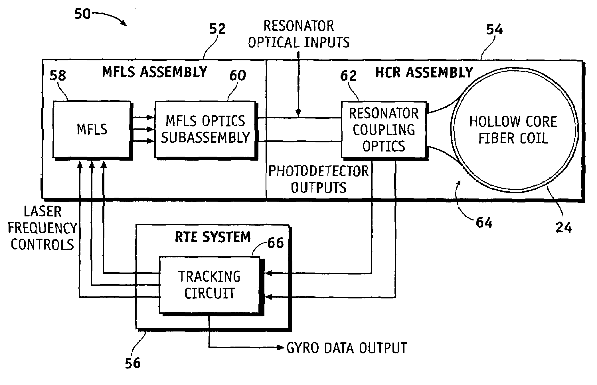
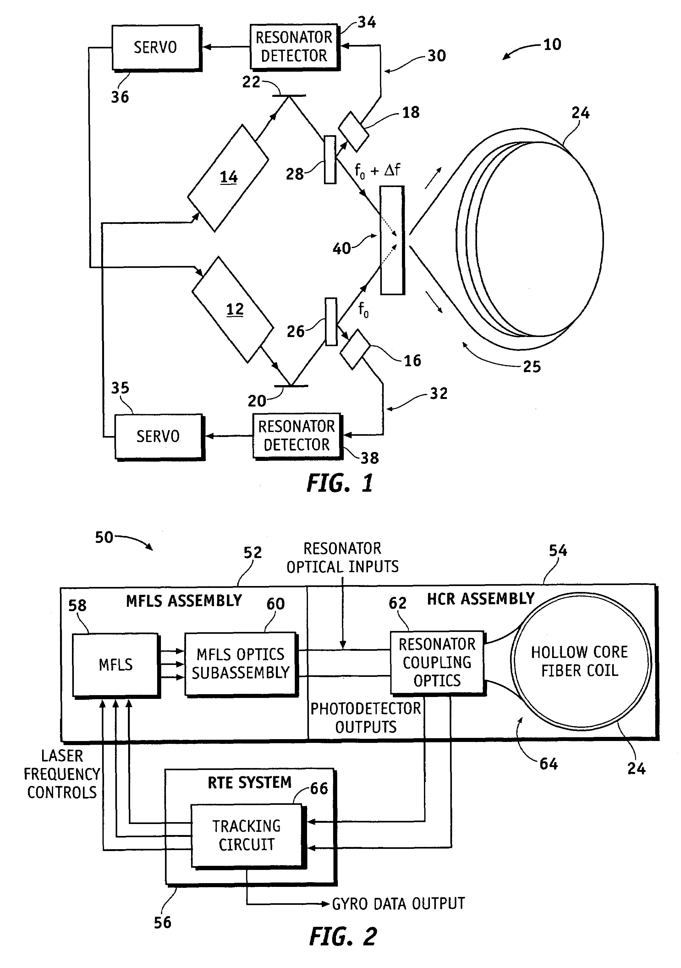
[0020]Referring now to the drawings, FIG. 1 is a block diagram of a resonator gyro 10 in accordance with an exemplary embodiment of the present invention. The resonator gyro 10 comprises tunable light sources 12, 14 (e.g., tunable lasers) that synthesize light beams, respectively, a resonator 25 circulating light beams in counter-propagating directions and having a recirculator 40 that introduces a portion of the light beams from the tunable light sources 12, 14 into the resonator 25, photodetectors 16, 18 that sample light circulating in the resonator 25, resonance detectors 34, 38 coupled to the photodetectors 18, 16, respectively, that de...


PUM


Abstract

Methods and apparatus are provided for stabilizing laser light sources of a resonator gyro. A resonator gyro comprises a first light source configured to produce a first input light, a second light source configured to produce a second input light, a resonator coupled to the first and second light sources, a resonance detection circuit coupled to the resonator, and a controller coupled to the resonance detection circuit and the first and second light sources. The resonance detection circuit detects a resonance frequency for each of the counter-propagating directions of the resonator. The controller tunes the first input light to a clockwise resonance frequency, and tunes the second input light to a counter-clockwise resonance frequency. A difference between the resonance frequencies is proportional to a rotational rate of the resonator gyro.

Description

FIELD OF THE INVENTION[0001]The present invention generally relates to gyro systems, and more particularly relates to resonance tracking using two or more light sources in resonator gyros and methods for controlling two or more light sources in resonator gyros.BACKGROUND OF THE INVENTION[0002]Gyros have been used to measure rotation rates or changes in angular velocity about an axis of rotation. A basic conventional fiber optic gyro (FOG) includes a light source, a beam generating device, and a coil of optical fiber coupled to the beam generating device that encircles an area. The beam generating device transmits light beams into the coil that propagate in a clockwise (CW) direction and a counter-clockwise (CCW) direction along the core of the optical fiber. Many FOGs utilize glass-based optical fibers that conduct light along a solid glass core of the fiber. The two counter-propagating (e.g., CW and CCW) beams experience different pathlengths while propagating around a rotating clo...

Claims


Application Information

Patent Timeline
Patent Type & Authority Patents(United States)
IPC IPC(8): G01C19/72
CPCG01C19/727
Inventor SANDERS, GLEN A.STRANDJORD, LEE K.
Owner HONEYWELL INT INC
Why Eureka
Try Eureka