Navigation apparatus and navigation method with image recognition

a navigation apparatus and image recognition technology, applied in the direction of navigation instruments, landing aids, instruments, etc., can solve the problems of not being able to navigate an aircraft body, having to spend a certain amount of time and labor for the measurement of absolute coordinates, and becoming complicated in the system structure of the aircraft body

Active Publication Date: 2008-05-13
SUBARU CORP
View PDF12 Cites 21 Cited by
  • Summary
  • Abstract
  • Description
  • Claims
  • Application Information

AI Technical Summary

Benefits of technology

[0009]An object of the present invention is to provide a navigation apparatus which is capable of obtaining positional information of an aircraft with respect to a predetermined target spot accurately and immediately, without using ground facilities or DGPS for navigation control.
[0012]According to the apparatus of the first aspect and the method of the second aspect, the image process calculating section calculates a relative position of the body with respect to a predetermined target spot by processing image information of the target spot obtained by the imaging section. Further, the navigation calculating section generates and outputs navigation information (positional information of the body and the like) based on an attitude angle and an acceleration of the body calculated by the inertial information detecting section and a relative position of the body calculated by the image process calculating section. In other words, by correcting information calculated by integrating the acceleration of the body measured by the inertial information detecting section, the information having a bias error, with the use of information regarding a comparatively accurate relative position of the body calculated with the image recognition process, it is possible to calculate more valid navigation information.
[0013]Therefore, without ground facilities for navigation control such as a microphone, a millimeter-wave radar apparatus and the like provided in the vicinity of the predetermined target spot, it is possible to accurately obtain navigation information from the body itself. As a result, even to a spot where ground facilities for navigation control are not provided, it is possible to navigate the body accurately. Further, since it is possible to accurately obtain the navigation information from the body itself without using DGPS, it is not necessary to measure an absolute coordinate of the target spot. Therefore it is possible to reduce labor and time for measuring the absolute coordinate. Further, since it is not necessary to provide a GPS receiver, it is possible to simplify the system structure. Furthermore, since it is not necessary to wait for the convergence of the DGPS solution, it is possible to obtain the navigation information immediately, and therefore it is possible to reduce flying hours and save the fuel.
[0016]According to the above-mentioned apparatus and method, information calculated by integrating the acceleration of the body measured by the inertial information detecting section, the information having a bias error, is corrected with the use of a comparatively accurate relative position of the body calculated by the image process calculating section, for calculating more valid navigation information (positional information of the body, and the like). Therefore, without using ground facilities for navigation control or DGPS, it is possible to obtain navigation information with respect to the target spot accurately and immediately from the body itself. As a result, it is possible to navigate the body accurately to a spot where ground facilities for navigation control are not provided. Further, it is possible to reduce labor and time for measuring an absolute coordinate, and moreover, it is possible to simplify the system structure. Further, it is possible to reduce flying hours and save the fuel.

Problems solved by technology

Therefore, it is not possible to navigate an aircraft body to a spot near which these ground facilities for the navigation control are not set.
Therefore, it is necessary to spend a certain amount of time and labor for the measurement of the absolute coordinate.
Further, since it is necessary to set a GPS base station for transmitting correction information for DGPS to the aircraft on the ground, a system structure thereof becomes complicated.
Therefore, flying time becomes longer and extra fuel is wasted unnecessarily.

Method used


Image

  • Navigation apparatus and navigation method with image recognition
  • Navigation apparatus and navigation method with image recognition
  • Navigation apparatus and navigation method with image recognition

Examples


Embodiment Construction

[0030]Hereinafter, an embodiment of the present invention will be described with reference to figures.

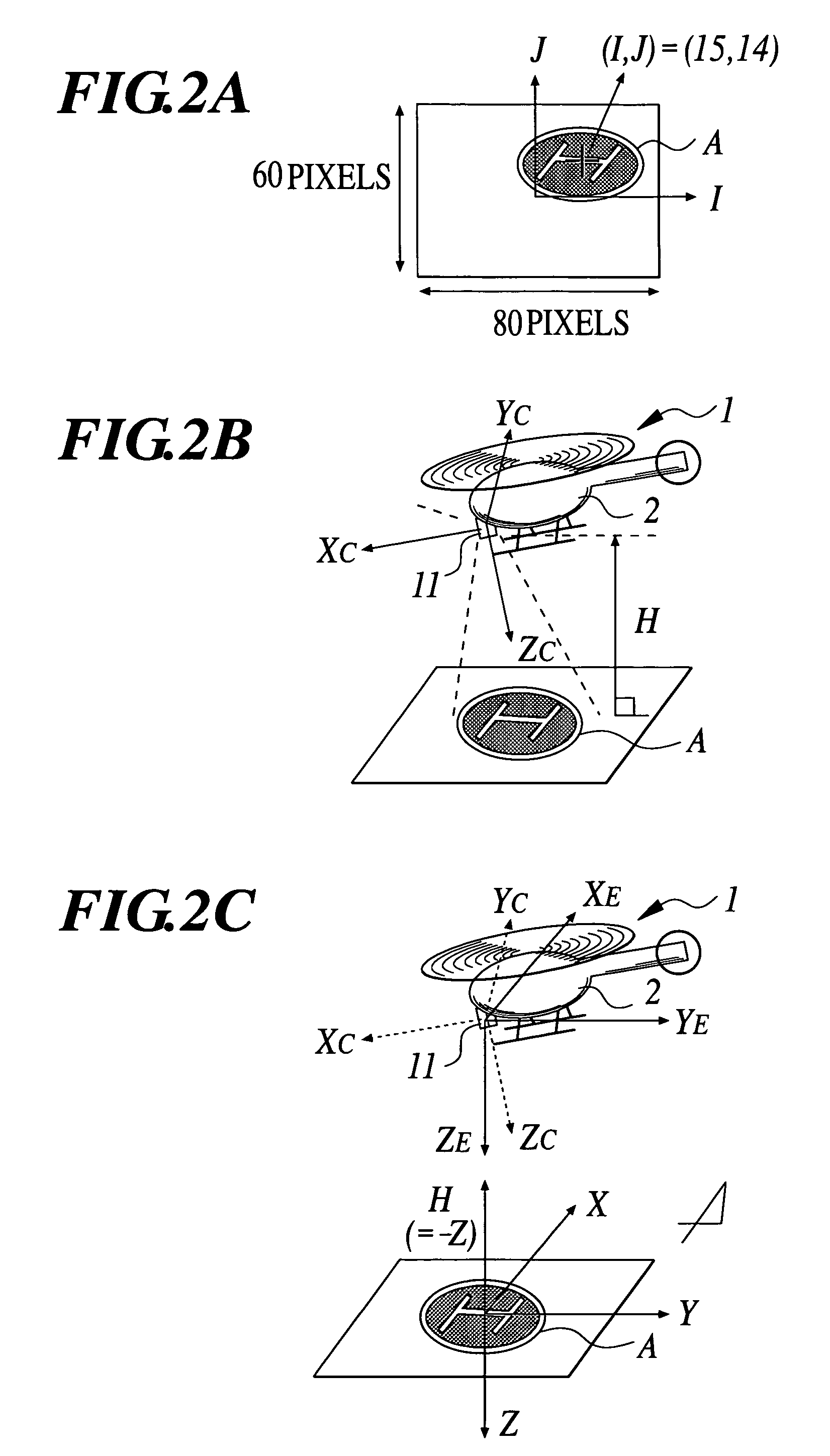
[0031]Here, it is assumed that a navigation apparatus 10 with image recognition according to the embodiment of the present invention is mounted on a manned helicopter 1 (see FIGS. 2B and 2C). On the helicopter 1, in addition to the navigation apparatus 10 according to the present embodiment, mounted are a GPS receiver for receiving positional information from a GPS satellite, an automatic operation apparatus which drives the helicopter on autopilot in response to the positional information or the like which is outputted from the navigation apparatus 10 (navigation output), and the like.

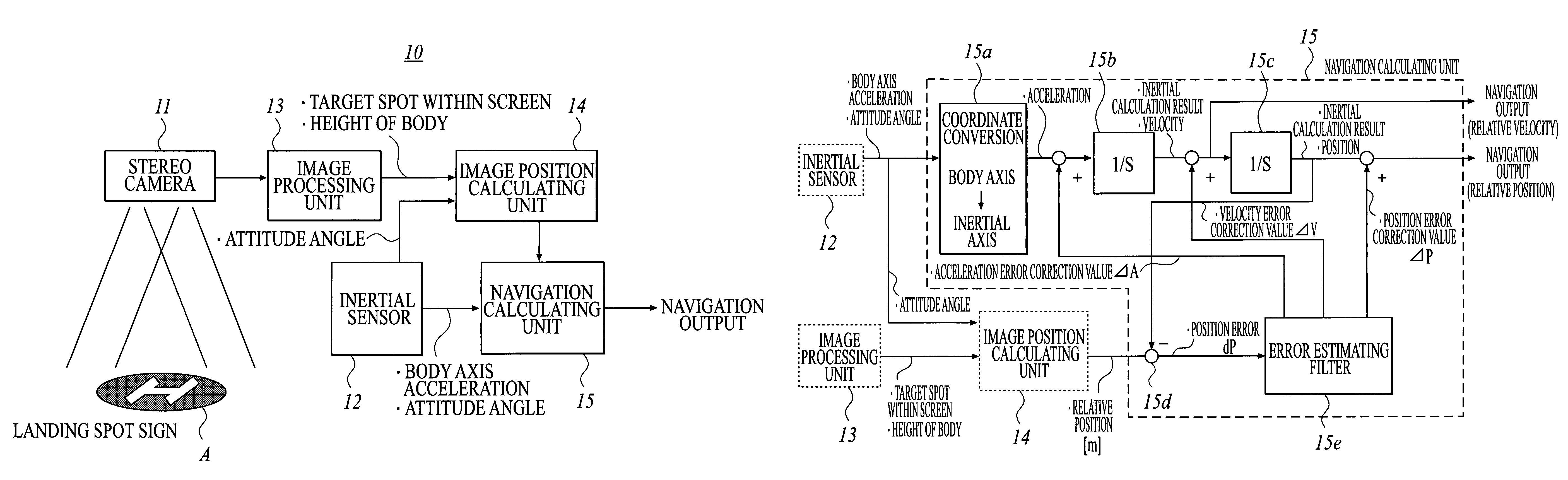
[0032]First, with reference to FIGS. 1 to 3, a structure of the navigation apparatus 10 according to the present embodiment will be described.

[0033]The navigation apparatus 10 comprises a stereo camera 11 which is fixed at the lower part of an aircraft body 2 of the helicopter 1 (see FIG. 2B), an iner...


PUM


Abstract

A navigation apparatus with image recognition, includes: an imaging section for obtaining a stereo image of a target spot; an inertial information detecting section for measuring an attitude angle of a body and an acceleration of the body; an image process calculating section for calculating a relative position of the body with respect to the target spot based on the stereo image and the attitude angle; and a navigation calculating section for calculating navigation information based on the attitude angle, the acceleration and the relative position.

Description

BACKGROUND OF THE INVENTION[0001]1. Field of the Invention[0002]The present invention relates to a navigation apparatus and a navigation method with image recognition.[0003]2. Description of Related Art[0004]So far, various technologies for navigating a vertical-takeoff aircraft such as a helicopter and the like to land on the ground (a ship) have been proposed.[0005]One proposed example of them is a technology for navigating a helicopter to a predetermined target spot by detecting sound wave generated from the helicopter with a microphone, by calculating a position of the helicopter based on an electric signal regarding the sound wave, and by transmitting the calculation result to the helicopter (see JP-Tokukaihei-8-7199A, Page 1, FIG. 1). Further, another proposed example of them is a technology for navigating a flying object to a predetermined target spot based on positional information of the flying object obtained by using a millimeter-wave radar apparatus or a stereo camera ap...

Claims


Application Information

Patent Timeline
Patent Type & Authority Patents(United States)
IPC IPC(8): G01C21/00B64D45/04G01C11/00G01C21/16G01C21/26G08G5/02
CPCG01C11/00G01C21/005G01C21/165G05D1/0676G05D1/0858G01C21/1656
Inventor YAMANE, AKIHIRO
Owner SUBARU CORP
Why Eureka
Try Eureka