
Rock bolt anchor having concurrent chemical and mechanical anchoring means and method for using the same

a technology of chemical and mechanical anchoring means and rock bolts, which is applied in the direction of fastening means, bulkheads/piles, dowels, etc., can solve the problems of resin package damage, resin package damage, and the inability of the writer to teach an integrated chemical-mechanical anchorag

Inactive Publication Date: 2008-05-20
MORRIS WILFRED G
View PDF16 Cites 6 Cited by
  • Summary
  • Abstract
  • Description
  • Claims
  • Application Information

AI Technical Summary

Benefits of technology

"The invention is a rock bolt anchor that combines chemical and mechanical means to fix a rock bolt into a drilled hole. The anchor has a spring loaded resin release mechanism that contains a package of adhesive resin for injection into the annulus between the rock bolt and the hole. The main body of the anchor has a threaded end for inserting into the hole and a hollow ported lance for delivering the resin. The resin package is pressurized so that it can be forced into the annulus. The invention has the advantage of controlling the flow of resin, taking advantage of the binding capabilities of the resin. The invention also has a threaded end for easy connection to a grouting material and a unique design that allows for faster installation and reduces installation time."

Problems solved by technology

However, Wright does not teach an integrated chemical-mechanical anchor, but rather describes a device where the resin package is placed in the drilled hole in advance of the rock bolt and then the rock bolt is inserted to pierce the package and permit the resin to flow around a portion of the rock bolt.
This can have the result of creating voids within the resin material and wasting resin adhesive that may flow down the drilled hole and merely coat the wall of the drilled hole rather than anchor the rock bolt to the wall of the drilled hole.
The effect is that the total adhesive capability of the resin is not achieved.
Secondly, the resin package is inserted into the drilled hole in advance of the rock bolt.
This means that the resin package could be damaged during insertion and tamping to the top of the hole.
Resin leakage will again result in the reduction of resin adhesive capability.

Method used


Image

  • Rock bolt anchor having concurrent chemical and mechanical anchoring means and method for using the same
  • Rock bolt anchor having concurrent chemical and mechanical anchoring means and method for using the same
  • Rock bolt anchor having concurrent chemical and mechanical anchoring means and method for using the same

Examples


Embodiment Construction

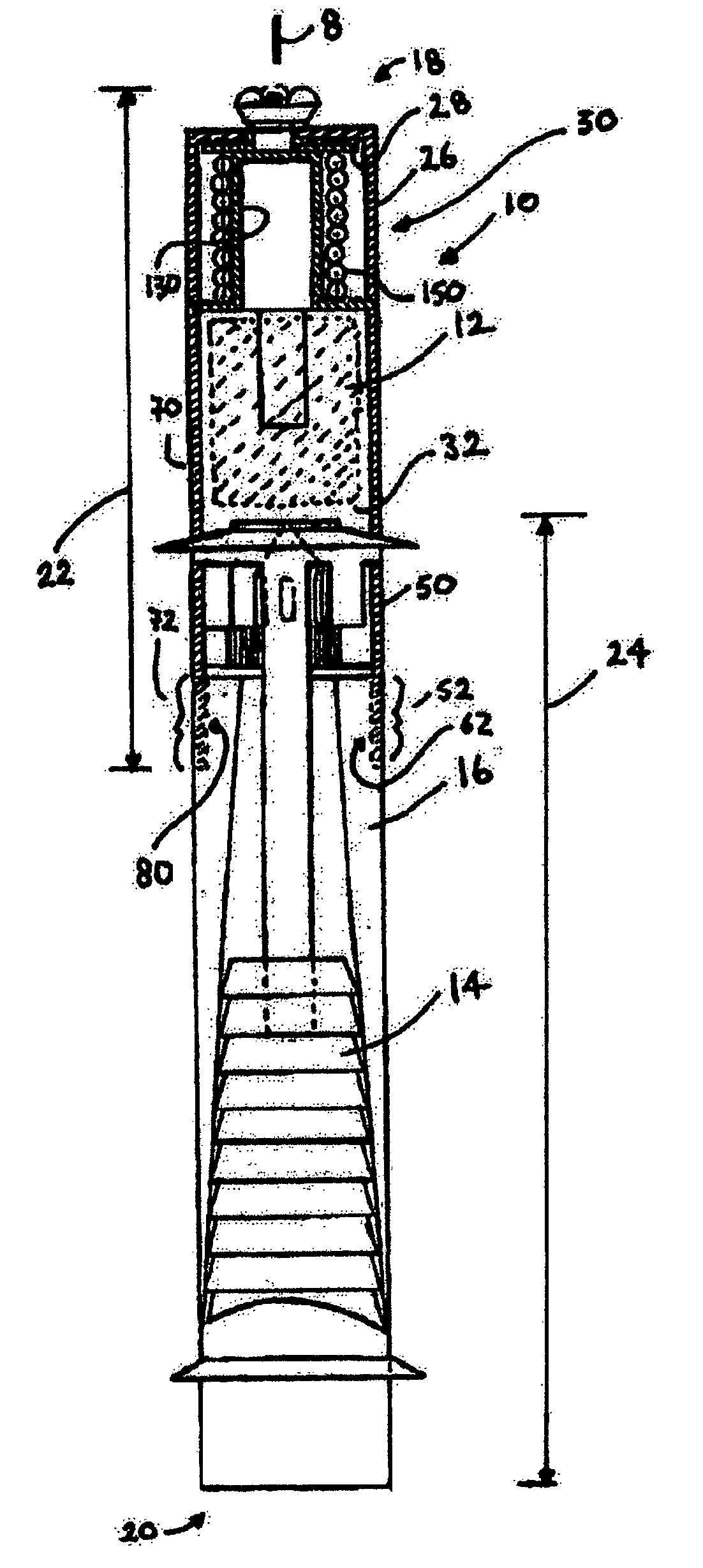
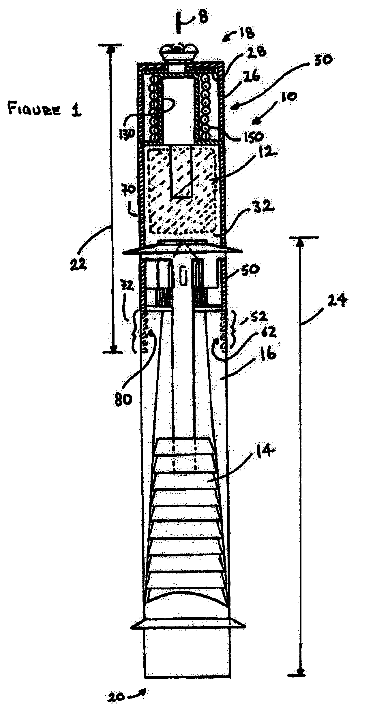
[0038]Referring now to FIG. 1, there is illustrated a preferred embodiment of my invention. My invention (10) is a rock bolt anchor having a combination of chemical means for fixing the rock bolt inside of a drilled hole and mechanical means for fixing the rock bolt inside of a drilled hole. The chemical means is a package of adhesive resin (12) shown in ghost lines. The mechanical means is a pair of opposed outer shells (14) carried by a main body (16). A major advantage and innovative feature of my invention is the combined chemical and mechanical means for anchoring the rock bolt which results in a three fold increase in anchoring strength over conventional anchoring means. The operation of both the chemical means and mechanical means will be more fully explained below.

[0039]Still referring to FIG. 1, for purpose of this description, the rock bolt and rock bolt anchor will always be considered to be oriented up (top of the page) and down (bottom of the page) as if inserted vertic...


PUM


Abstract

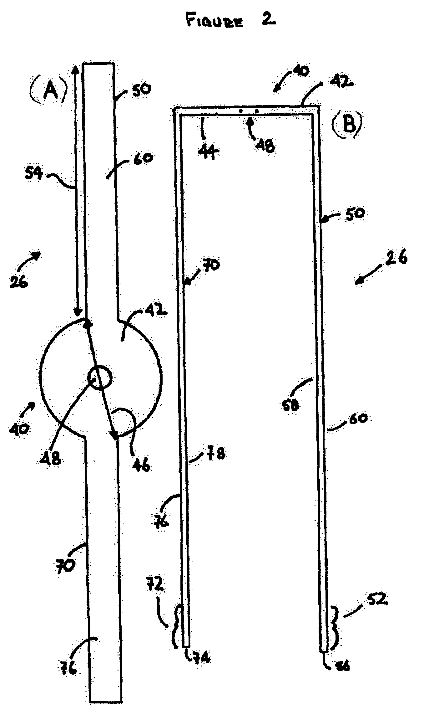
A rock bolt anchor includes a top portion permanently fixed to a bottom portion. The top portion carries a package of resin. A spring-loaded mechanism pressurizes the package and forces the resin out when the package is lanced. The bottom portion main body carries a pair of opposed outer shells in a dovetail joint on opposed tapers. The annulus adjacent to the rock bolt anchor is sealed by top and bottom bulkheads. The bottom portion is threaded onto a rock bolt. A hollow and ported lance is threaded onto the exposed end of the rock bolt. The combination is inserted into a drilled hole and the rock bolt rotated. The lance rises and pierces the package releasing into the sealed annulus. Continued rotation of the rock bolt, forces the main body down and the outer shells up the tapers compressing them against the wall of the drilled hole.

Description

CROSS-REFERENCE TO RELATED APPLICATIONS[0001]This application claims the benefit of my co-pending Canadian patent application entitled “Dual Mechanical & Resin Anchor Bolt” filed in the Canadian Intellectual Property Office on Jun. 30, 2004 and having a serial number of 2,470,212.REFERENCE TO MICROFICHE APPENDIX[0002]Not applicable.BACKGROUND OF THE INVENTION[0003]1. Field of the Invention[0004]This invention relates to a rock stabilizing apparatus for anchoring unstable rock formations in underground mines and construction sites and more particularly relates to an apparatus and method that concurrently employs both chemical and mechanical anchor means to anchor a rock bolt within an unstable rock formation.[0005]2. Background of the Invention[0006]It is well known in mining and construction operations to reinforce roofs, sides and floors of tunnels and shafts using rock bolting. The rock bolts are inserted into a drilled hole and are anchored in place chemically by either a quick c...

Claims


Application Information

Patent Timeline
Patent Type & Authority Patents(United States)
IPC IPC(8): E21D20/02E02D5/80E21D21/00
CPCE02D5/808E21D20/025E21D21/008
Inventor MORRIS, WILFRED G.
Owner MORRIS WILFRED G
Learn More