Structured cabling system and method

Active Publication Date: 2008-05-20
HELLERMANNTYTON DATA
17 Cites 4 Cited by

AI-Extracted Technical Summary

Problems solved by technology

The existing method of installing structured cabling, as outlined above, has a number of well recognized disadvantageous.
Notably, termination of the cable to the patch panel and remote jack is somewhat problematic under site conditions.
The time required on site to install the structure cabling system is considerabIe, resulting in general inconvenience and cost.
On-site testing ...

Benefits of technology

[0007]We have now devised an arrangement which overcomes many of the difficulties and shortcomings outlined above. The preferred embodiment of the present invention provides a structured cabling system in which all the required termination and testing is carried out under factory conditions. Forming terminations to the required standard under factory conditions is substantially easier than attempting to carry out termina...

Abstract

A structured cabling system includes a plurality of data cables (6A-6F), one end of each cable being secured to a jack of a multiple jack assembly (1) and the other end of each cable being secured to an individual jack (9A-9F) located within a protective enclosure (11). The individual cables are mechanically secured to at least the protective enclosure (11) and/or a strain relief member (8) within the cable bundle is secured to the protective enclosure (11). The entire assembly may be pre-formed under factory conditions and delivered to an installation site. The multiple jack assembly (1) may then be secured, preferably by snap-fitting, to a rack assembly and the protective enclosure (10) may be used to draw the entire cable length to the required position. Once the cable is in position the protective enclosure (10) is discarded and the jack secured to their final use positions. In an alternative embodiment the protective enclosure forms a housing for jacks (9A-9F) in their final use position and may, for example, be snap-fitted to a floor box for this purpose.

Application Domain

Technology Topic

Strain reliefMechanical engineering +1

Image

  • Structured cabling system and method
  • Structured cabling system and method
  • Structured cabling system and method

Examples

  • Experimental program(1)

Example

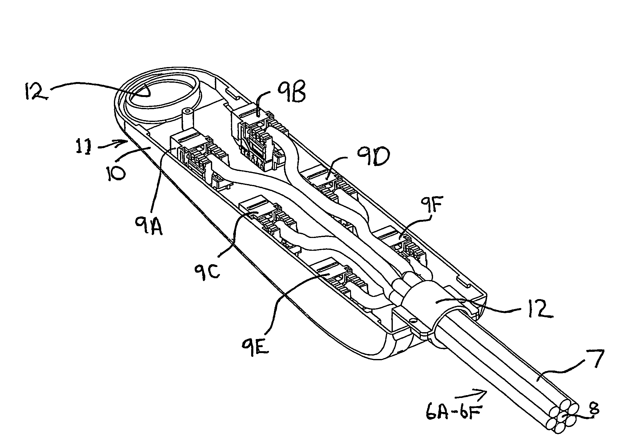
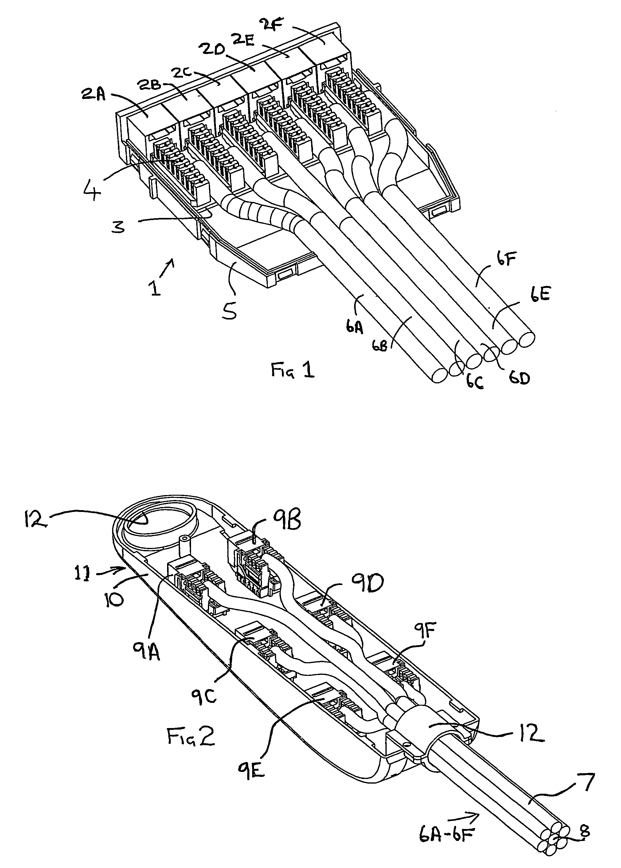
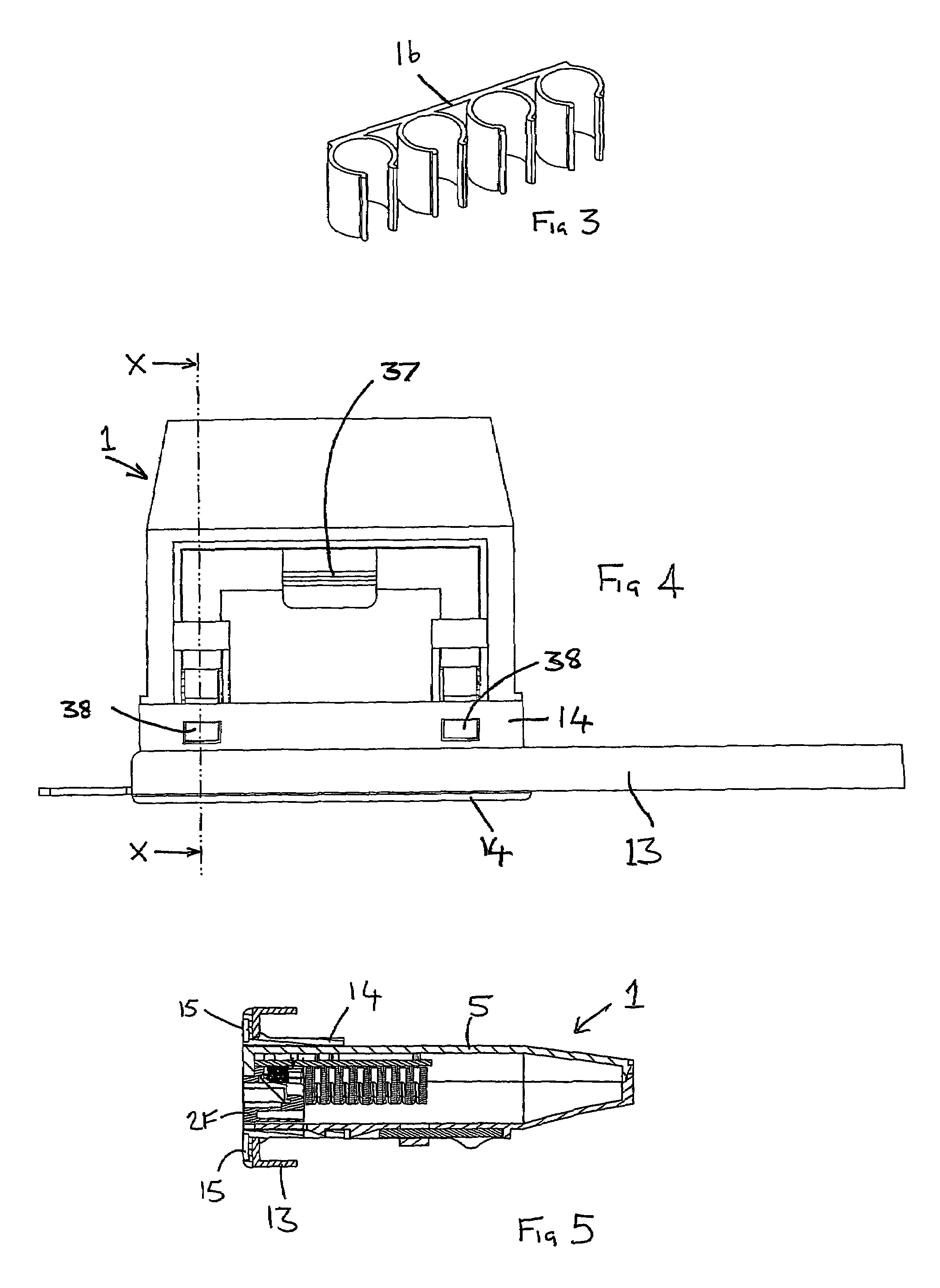
[0023]Referring firstly to FIG. 1 there is illustrated a multiple jack assembly 1 comprising six individual jacks 2A-2F. Each jack is mounted on a printed circuit board (PCB) 3 and is provided with a respective integrated desktop connector (IDC connector) 4. The jacks and PCB are mounted within a casing 5, only the base of which is shown in FIG. 1. In use, the casing 5 will also include a cover which is a snap-fit with the base so as to enclose the jacks, the PCB and IDC connectors. The snap-fit between the base and the cover of the casing may grip the individual data cables 6A-6F to provide strain relief. Alternatively, the individual cables may be clamped to the base by suitable clamping means. Six data cables 6A-6F are terminated to respective IDC connectors of the jacks 2A-2F to the standard required (typically Cat 5, Cat 5e or Cat 6) by the installation in question, such that the eight individual wires in each data cable are connected to respective contacts of the jack to which the data cable is connected. As usual, each jack will accept a separate plug (e.g., an RJ45 plug) so that the wires in each plug become electrically connected exclusively to associated wires in the jack in which it is inserted. The termination, and the securing of the casing cover to the casing base are completed under factory conditions.
[0024]Referring now to FIG. 2, the end regions of the data cables 6A-6F remote from that illustrated in FIG. 1 is shown. It will be noted that the individual cables are formed into the composite cable 7 which preferably in addition to the individual cables 6A-6F includes a central strain relief element 8. The individual data cables 6A-6F are respectively terminated to individual jacks 9A-9F via associated IDC connectors. The individual jacks are located and optionally temporarily secured within the base 10 of a protective enclosure 11. The composite cable 7 is secured to the base by means of a clamp 12 to ensure stress relief. Additionally or alternatively, the strain relief element 8 may be secured to the base 10 of the protective enclosure to provide strain relief. This strain relief element 8 may optionally be secured to the casing 5 of the possible jack assembly 1 to provide strain relief at that point.
[0025]In use, the protective enclosure 11 would be closed by means of a cover which forms a snap-fit with the base 10. The enclosure protects the individual jacks 9A-9F and allows strain to be applied to the composite cable without applying strain to the terminations of the individual cables to the IDC connectors. Preferably, a pulling eye 12 is formed in the protective enclosure to allow a pulling rope to be attached to the protective enclosure. Alternatively, if appropriate strain relief is provided at the multiple jack assembly end, a pulling rope may be attached to the multiple jack assembly to enable the multiple jack assembly to be pulled towards its eventual location.
[0026]The exact point at which the individual data cables 6A-6F are formed into the composite cable 7 will depend on the nature of the data installation in question. However, over he majority of the distance between the multiple jack assembly 1 and the protective enclosure 11 the cables will be in the form of a single composite cable to facilitate easy handling of the complete assembly. In some instances, the act of laying the individual cables will form a composite cable of the required structural integrity. However, in general it is envisaged that some means would be provided for holding the composite cable in its composite form. Such means may, for example include over-wrapping of the cable with a suitable film material. The means used for holding the cable into its composite form will be chosen having due regard to the need to be able to bend the composite cable without imposing undue strain on any one individual cable within the composite.
[0027]Termination of the individual data cables to the individual Jacks 9A-9F, i.e., the connection of the individual wires in the data cables to respective contacts of the jacks, and subsequent testing, is accomplished under factory conditions.
[0028]Once a complete cabling assembly comprising multiple jack assembly, data cables, individual jacks and protective enclosures has been formed and tested under factory conditions, it will be transported to site. To this end, a carrier is preferably provided. The carrier preferably includes a drum for receiving the data cables and means for accommodating and holding the multiple jack assembly and the protective enclosure. Several complete cable assemblies may be mounted on the same delivery device depending on their length. The carrier is transported to site by any suitable means, for example, road transport, and is taken to the general area where the structured cabling installation is required. In general, a rack arrangement will be provided in a comms room or cabinet. In the case of the preferred embodiment of the present invention, the rack is provided with a plurality of individual housings 13 (FIG. 4) into each of which several multiple jack assemblies can be mounted. The required mounting is preferably obtained by offering the multiple jack assembly 1 up to the rear of the housing 13. In the preferred embodiment of the invention a plastic adaptor 14, which may incorporate labeling facilities 15, is offered up to the housing 13 from the front thereof, and the multiple jack assembly 1 is then pushed into snap-fit engagement with the adaptor 14 from the rear of the housing. This arrangement is illustrated in FIG. 5. A release lever 37 is provided which will enable the multiple jack assembly to be released from its associated housing by sliding the release lever to disengage the snap-fit latches 38. The fact that the multiple jack assembly can be offered up to the housing 13 from the rear thereof, combined with the above described latching arrangement, and the sliding release lever, greatly assist installation and removal of the multiple jack assembly from the comms cabinet. It will be appreciated that in a complete structured cabling installation many cables will be located within the comms cabinet and the facility easily to insert and release an individual multiple jack assembly from the rear is of considerable value. The latch 38 and sliding release lever 37 arrangement may, in fact, be of general utility in applications other than the structured cabling assembly described herein.
[0029]Having snap-fitted a multiple jack assembly 1 into tie correct position in the associated housing 13, the data cables are guided through the communication enclosure by conventional means or by use of special purpose clips 16 as illustrated in FIG. 3. The remainder of the cable assembly, including the individual jacks 9A-9F is then hauled through the building structure to a point adjacent to the required final position of the jacks (9A-9F). The protective enclosure is then removed and the individual data cables unlaid from the composite cable to bring the jacks to their required final position. The jacks will then be snap-fitted into appropriate mounting in floor or wall boxes.
[0030]It will be appreciated that the entire data installation process, as outlined above, can be effected on site without disturbing the terminations between the data cables and their associated jacks. Further, no on-site testing of the completed installation is necessary.
[0031]Although in general it will be desirable to start the cable laying exercise from the comms cabinet/comms room by installing the multiple jack assembly to its associated housing and then laying the cable to the required position, it is to be understood that under certain circumstances it may be desirable to start the cable laying exercise at the individual jack end of the assembly and lay the cable to the comms cabinet/comms room where the multiple jack assembly is secured in position.
[0032]In one embodiment of the invention the data cables are provided in pairs connected together on a common line in a generally “8” shaped cross-sectional arrangement. In order to provide the six cables of the illustrated embodiment of the invention, three such double “8” cables are laid around the strain relief member 8. The resultant bundle may be secured together by any appropriate means, for example, adhesive bonding or binding. In the case of a six cable arrangement as illustrated, the three different “8” shaped cable pairs may be of different colours. One data cable of each pair preferably includes an appropriate indicator, for example a continuous or near continuous line of printed text. By this means each individual jack 9 can readily be associated with a particular one of the jacks of the multiple jack assembly by visual inspection.
[0033]In an alternative embodiment of the invention six individual cables are laid about a central strain relief member. The individual cables can be of any suitable type. Preferably, the cables are provided with end-to-end identification means, for example in the form of a continuous printed legend on each cable or in the form of coloured or raised identification strips or bumps. This will assist in identifying which jack of the multiple jack assembly is connected to which of the individual jacks at the remote end of the cable assembly. However, use of identifying characteristics on the cables is not essential if all termination is carried out under factory conditions. Preferably, each of the jacks has associated therewith indicia which may be used to identify which of the jacks at the multiple jack assembly is connected to which of the jacks at the remote end of the structured cable assembly. The indicia may be in the form of a labeling system. Preferably, the label or labels of the multiple jack assembly are visible from the rear of the assembly so that they can be viewed from the rear of the comms cabinet.
[0034]In some applications, for example those using Cat 6 cable, it may be desirable to position the individual cables within the bundle to reduce alien cross-talk. For example, it may be desirable to lay the cables in an A-B, A-B, A-B sequence around the strain relief member.
[0035]Referring now to FIG. 6 an alternative arrangement for the end of the structured cabling system remote from the multiple jack assembly is shown. The arrangement shown in FIG. 6 may be used instead of the arrangement shown in FIG. 2. In the FIG. 6 arrangement, six individual jacks 20A-20F are respectively connected using conventional IDC connectors to respective data cables 21A-21F which are laid about a strain relief element 22. The data cables 21A-21F and strain relief element 22 together form a composite cable 23. The individual jacks 20A-20F are mounted on a protective enclosure 24, which protects the terminations of the data cables 21A-21F to the respective jacks 20A-20F. The protective enclosure 24 is mechanically secured by a suitable clamp 25 to the composite cable 23. Preferably, the strain relief element 22 is secured directly to the protective enclosure 24. As a result, a pulling force may be exerted on the cable 23 by grasping the protective housing 24 and pulling. The individual connections between the data cables 21A-21F and the individual jacks 20A-20F are isolated from such pulling forces by virtue of the connection between the strain relief element 22 and the protective enclosure 24 and by virtue of the clamp 25. With the arrangement of FIG. 6, when the cabling system has been run to the correct position, the jacks 20A-20F and the protective enclosure 24 are snap fitted as a unit into a suitable housing, for example a suitable floor box. To this end, snap-fit latches 26 are preferably provided as part of the individual jack/protective enclosure assembly.
[0036]In an alternative embodiment (not shown), the ends of the cables remote from the multiple jack assembly are not terminated to jacks. Accordingly, the structured cabling system as supplied comprises a plurality of cables ach terminated to a multiple jack assembly, the cables being bundled with a strain element to enable the bundle cable to be drawn into the required position. With such an arrangement, individual termination is necessary on site, but such termination is restricted to the ends of the data cable remote from the comms cabinet or room.
[0037]In yet a further alternative embodiment both ends of the cable are terminated in multiple jack assemblies each substantially identical to the other. Both multiple jack assemblies are preferably of the form illustrated in FIG. 1. With such an arrangement, both multiple jack assemblies will be secured to respective housings either within the same rack structure or within different rack structures, possibly in different comms rooms. Such an arrangement will allow very rapid establishment of data connections between rack systems.
[0038]It is envisaged that, in many instances, each cable assembly will be manufactured to a specific length determined by the particular installation. Such specific lengths may be identified by site survey or from scaled plans of the proposed installation site. It is envisaged, however, that cable assemblies may be manufactured in a range of predetermined standard lengths. It is expected that manufacture of assemblies to predetermined standard lengths will be somewhat more economic than individual manufacture to specific lengths and in the circumstances where standard length cables may be utilized for a particular installation this may provide a more economic solution to the installation problem than the use of individually manufactured cables.
[0039]Referring now to FIG. 7, there is shown a schematic view or part of a Comms cabinet suitable for use with the system described above. For the purposes of illustration only two multiple jack assemblies 1 are illustrated mounted on respective housings 13. It will be appreciated that, in a typical installation, there will be a large number of housings 13 each of which will accommodate several multiple jack assemblies. The illustrated Comms cabinet 30 comprises, in addition, a plurality of wire grids 31. Only one such grid 31 is illustrated in FIG. 7, but it will be appreciated that, in general, both sides 32, 33 of the Comms cabinet will be furnished with such grids. In addition, intermediate grids may be located in a central region of the cabinet The grids 31 provide a convenient means for locating the data cables 34 of the structured cabling system illustrated. To his end, purpose designed clips 35 may be secured to the grids (eg by snap fitting) and provide clip structures for receiving the data cables 34. Conveniently, each clip 35 may include one or more clipping areas each of which is adapted to receive the data cables of one structured cabling system. Using such a grid and clip arrangement cable management within the comms cabinet 30 may quickly and easily be effected. If additional local restraint of cables within the comms cabinet is required, or if the comms cabinet is intended to include cabling other than the structured cabling system described above, the grids 31 provide a convenient means whereby cables may be secured by means of clips or cable ties.
[0040]Whilst the invention has been described with particular reference to copper cabled arrangements it will be appreciated that the principles of the present invention may be applied to optical fibre arrangements if an optical fibre system is required.

PUM

no PUM

Description & Claims & Application Information

We can also present the details of the Description, Claims and Application information to help users get a comprehensive understanding of the technical details of the patent, such as background art, summary of invention, brief description of drawings, description of embodiments, and other original content. On the other hand, users can also determine the specific scope of protection of the technology through the list of claims; as well as understand the changes in the life cycle of the technology with the presentation of the patent timeline. Login to view more.

Similar technology patents

Methods of Suppressing Adaptor Dimer Formation in Deep Sequencing Library Preparation

InactiveUS20220119805A1Quickly and accuratelyMicrobiological testing/measurementDNA preparationDeep sequencingDouble strand dna
Owner:MT SINAI SCHOOL OF MEDICINE

Diagnostic kit for sepsis and diagnosis method using same

PendingUS20200217798A1Low morality rateQuickly and accuratelyMicrobiological testing/measurementRaman scatteringOligonucleotidePathogen
Owner:KOREA RES INST OF CHEM TECH

Test result verification method, device and equipment and computer readable storage medium

PendingCN109684193AAvoid error rateQuickly and accuratelySoftware testing/debuggingComputer engineeringAPI testing
Owner:ONE CONNECT SMART TECH CO LTD SHENZHEN

Compression Molding Apparatus

InactiveUS20170072603A1Quickly and accuratelyMaterials scienceProjector
Owner:CHAEI HSIN ENTERPRISE CO LTD

Composition for cancer diagnosis

PendingUS20220326243A1Quickly and accuratelyEarly diagnosisMicrobiological testing/measurementBiological material analysisCancers diagnosisCancer research
Owner:ACURASYSBIO CO LTD

Classification and recommendation of technical efficacy words

  • Quickly instal
  • Quickly and accurately

Method and apparatus for installing a wireless security system

InactiveUS20080094204A1Quickly instalTransmissionBurglar alarmSafe systemWireless security
Owner:ROBERT BOSCH GMBH +1

Method and injection molding machine having a modular structure

InactiveUS20090291162A1Quickly instalFood shapingModularityModular structure
Owner:NETABTAL MASCHEN

Centerline-based pinch/bridge detection

ActiveUS20060271906A1Low computational costQuickly and accuratelyOriginals for photomechanical treatmentSpecial data processing applicationsEngineeringLithography
Owner:SYNOPSYS INC

Systems and Methods of Using Labels for Evaluation of Produce and Other Foods

InactiveUS20160307040A1Quickly and accuratelyOvercomes shortfallImage enhancementImage analysisBiological productWideband
Owner:APPLICOLOR INC

Digital archery sight

InactiveUS20080289201A1Quickly and accuratelyBows/crossbowsSighting devicesStatorEngineering
Owner:SUPERIOR DESIGN

Self-service payment device and control method thereof

ActiveUS20190172296A1Quickly and accuratelyRegistering coin as creditCoin-freed apparatus detailsRadio frequencyEngineering management
Owner:ADVANCED NEW TECH CO LTD
Why Eureka
Try Eureka