Method and apparatus for reducing or eliminating stray light in an optical test head

a technology of optical test head and optical lens, which is applied in the direction of optically investigating flaws/contamination, material analysis, instruments, etc., can solve problems such as noise in output signals reduce stray light, and reduce stray light , the effect of reducing the reflection off the lens

Inactive Publication Date: 2008-05-20
WESTERN DIGITAL TECH INC
View PDF25 Cites 73 Cited by
  • Summary
  • Abstract
  • Description
  • Claims
  • Application Information

AI Technical Summary

Benefits of technology

[0013]In lieu of or addition to the above-mentioned layer, an anti-reflective coating can be placed on one or more of the lenses to reduce reflection off of the lens. This also reduces undesired stray light.
[0014]In lieu of or in addition to the above-mentioned layer and antireflective coating, one or more masks are provided in one or more of the optical paths for reducing or eliminating stray light. (As used herein, the term “mask” includes a mask having an adjustable aperture, i.e. an iris.)
[0015]In one embodiment, one or more masks are provided in one or more output paths to reduce or eliminate unwanted diffracted light caused by the texture formed on the substrate. In another embodiment, the apparatus is used to inspect an untextured disk comprising a pattern formed on the disk for discrete track recording. In such an embodiment the masks can reduce or eliminate diffracted light caused by the pattern. (The diffracted light typically emanates from the spot where the laser beam strikes the substrate. In contrast, the masks, antireflective coating and absorbing / trapping layer reduce or eliminate undesired light that does not emanate from the spot where the laser beam strikes the substrate.)

Problems solved by technology

Unfortunately, certain undesired light can introduce noise into output signals generated by optical test apparatus.

Method used


Image

  • Method and apparatus for reducing or eliminating stray light in an optical test head
  • Method and apparatus for reducing or eliminating stray light in an optical test head
  • Method and apparatus for reducing or eliminating stray light in an optical test head

Examples


Embodiment Construction

[0039]The specification below describes an optical head comprising novel structures for reducing stray light (and thus the noise that this light would otherwise cause). Although specific embodiments of the head are discussed in great detail, the above-mentioned structures for reducing stray light can be employed in other types of optical test apparatus (e.g. heads as discussed in the above-mentioned Treves patents).

I. Overview of Optical Inspection Apparatus 10

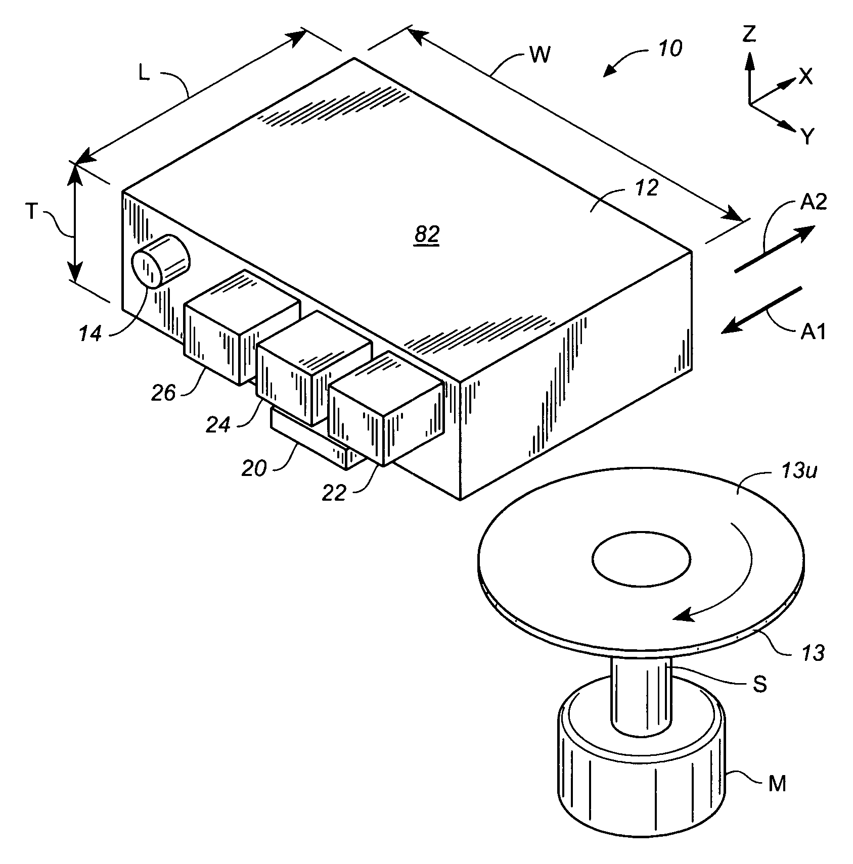
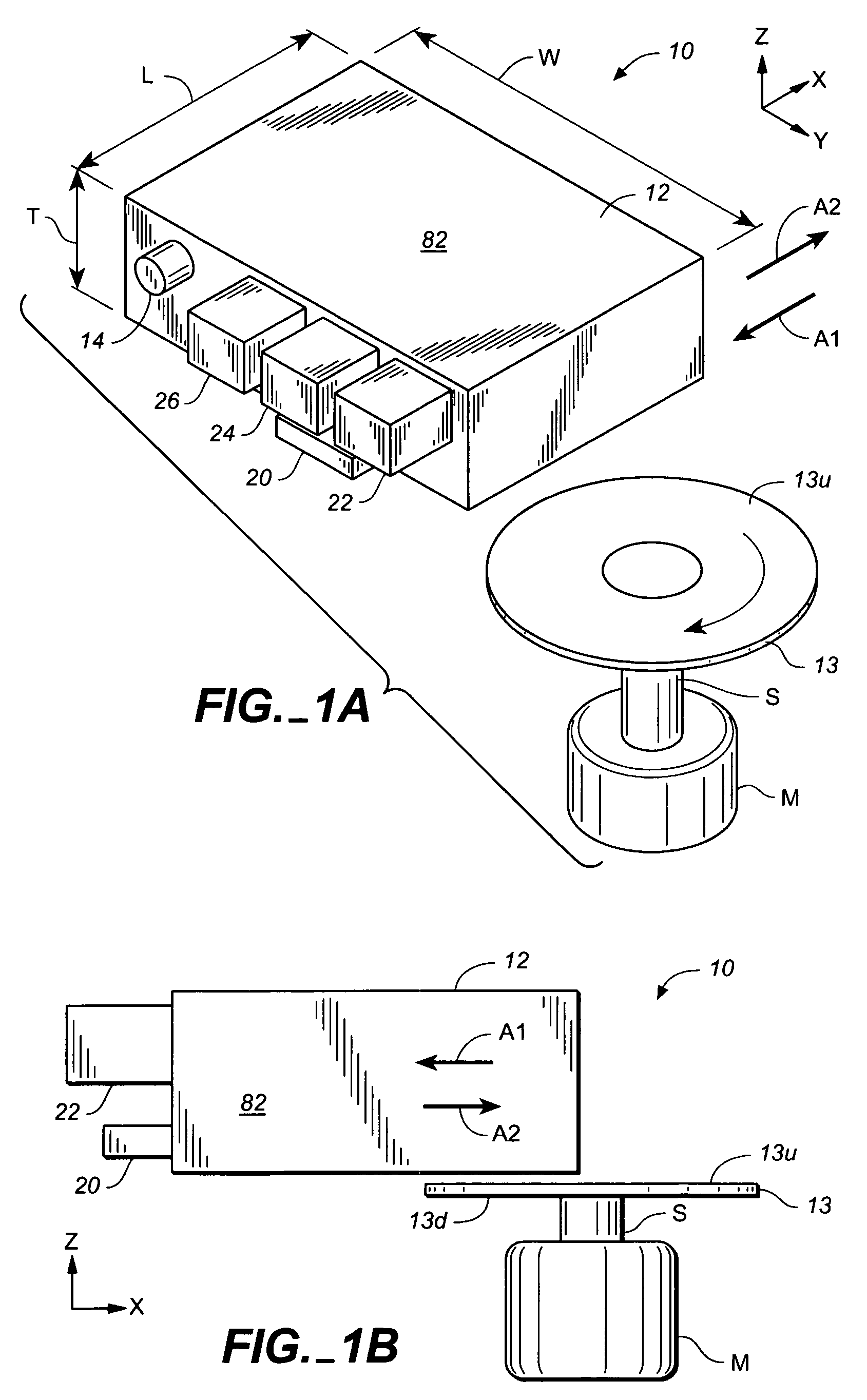
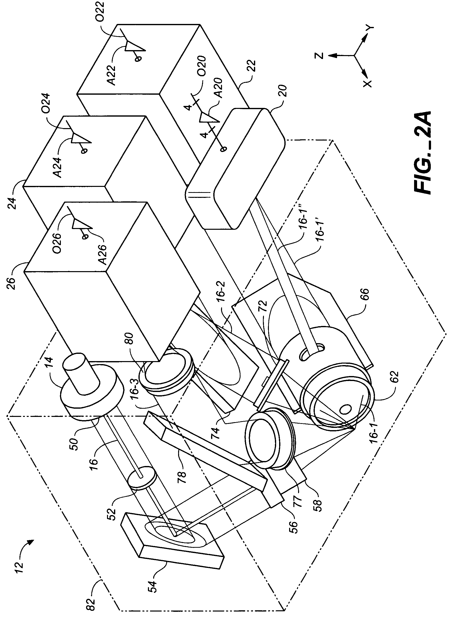
[0040]FIGS. 1A, 1B, 2A and 2B schematically illustrate an example of an optical inspection apparatus 10 in accordance with the invention that includes a head 12 for optically inspecting a top surface 13u of a workpiece 13 (typically a platter). (FIGS. 1A and 1B show the exterior of head 12 in schematic form. The actual appearance of head 12, in one embodiment, is shown in FIGS. 3A to 3D. FIGS. 2A and 2B show the optical paths and elements within head 12.) Head 12 comprises a laser source 14 for providing a laser beam 16. Head ...


PUM

PropertyMeasurementUnit
reflectivityaaaaaaaaaa
angleaaaaaaaaaa
angleaaaaaaaaaa

Abstract

An optical test head comprises one or more optical input paths by which a beam of light is communicated from a light source to a workpiece and one or more optical output paths by which light reflected off of the workpiece is communicated to a detector. The input optical path and the output optical path can include one or more mirrors and one or more lenses. At least one of the optical paths includes a layer for trapping and / or absorbing stray light. One or more of the lenses includes an anti-reflective coating for reducing noise caused by unwanted light reflection off of the lenses. The optical paths include one or more masks reducing stray light. The one or more masks can have an adjustable aperture (e.g. an iris).

Description

CROSS-REFERENCE TO PROVISIONAL PATENT APPLICATION[0001]This application claims priority based on U.S. provisional patent application No. 60 / 643,748, filed Jan. 13, 2005.BACKGROUND OF THE INVENTION[0002]This invention relates to methods and apparatus for optically inspecting workpieces such as substrates used to make magnetic disks or magnetic disks during any point in the manufacturing process (including the finished disk). This invention also pertains to methods for making such apparatus.[0003]Magnetic disks are typically manufactured using the following method.[0004]1. A disk-shaped substrate (typically an Al alloy) is lapped or ground.[0005]2. A material such as a nickel phosphorus alloy is plated onto the substrate.[0006]3. The plated substrate is polished and textured. (During texturing, texture grooves are typically formed in the substrate by mechanical abrasion to cause a subsequently deposited magnetic layer to exhibit anisotropy. It is also known to laser texture substrates...

Claims


Application Information

Patent Timeline
Patent Type & Authority Patents(United States)
IPC IPC(8): G01N21/86G01N21/88
CPCG01N21/55G01N21/95G01N21/9501G01N21/9506G01N2021/473
Inventor TREVES, DAVIDO'DELL, THOMAS A.
Owner WESTERN DIGITAL TECH INC
Why Eureka
Try Eureka