Inductive battery charger

a battery charger and inductive technology, applied in the field of inductive battery chargers, can solve the problems of kories' most likely risking damage to current mobile device designs, unable to allow device independence, and limited time period

Inactive Publication Date: 2008-05-20
MICROSOFT TECH LICENSING LLC
View PDF12 Cites 888 Cited by
  • Summary
  • Abstract
  • Description
  • Claims
  • Application Information

AI Technical Summary

Problems solved by technology

This time period is limited to the type of battery and other factors.
Unwanted flux could be sent to metallic objects or cause other problems.
Further, the system of Kories would most likely risk damage to current mobile device designs and does not allow for device independence for powering, because the power supply part must be part of the laptop computer.
Thus, the system of Kories is undesirable, and has limited use, if any, for recent battery packs designs.
Unwanted flux could be sent to metallic objects or cause other problems.
Thus, the system Rohde is undesirable, and limited use, if any, use for recent battery packs designs.

Method used


Image

  • Inductive battery charger
  • Inductive battery charger
  • Inductive battery charger

Examples


Embodiment Construction

[0020]The following description is divided into sub-sections to assist the reader. The subsections include Overview; Charging System Environment; Illustrative Data Structure; Illustrative Operational Environment; and Alternative Charging Systems.

Overview

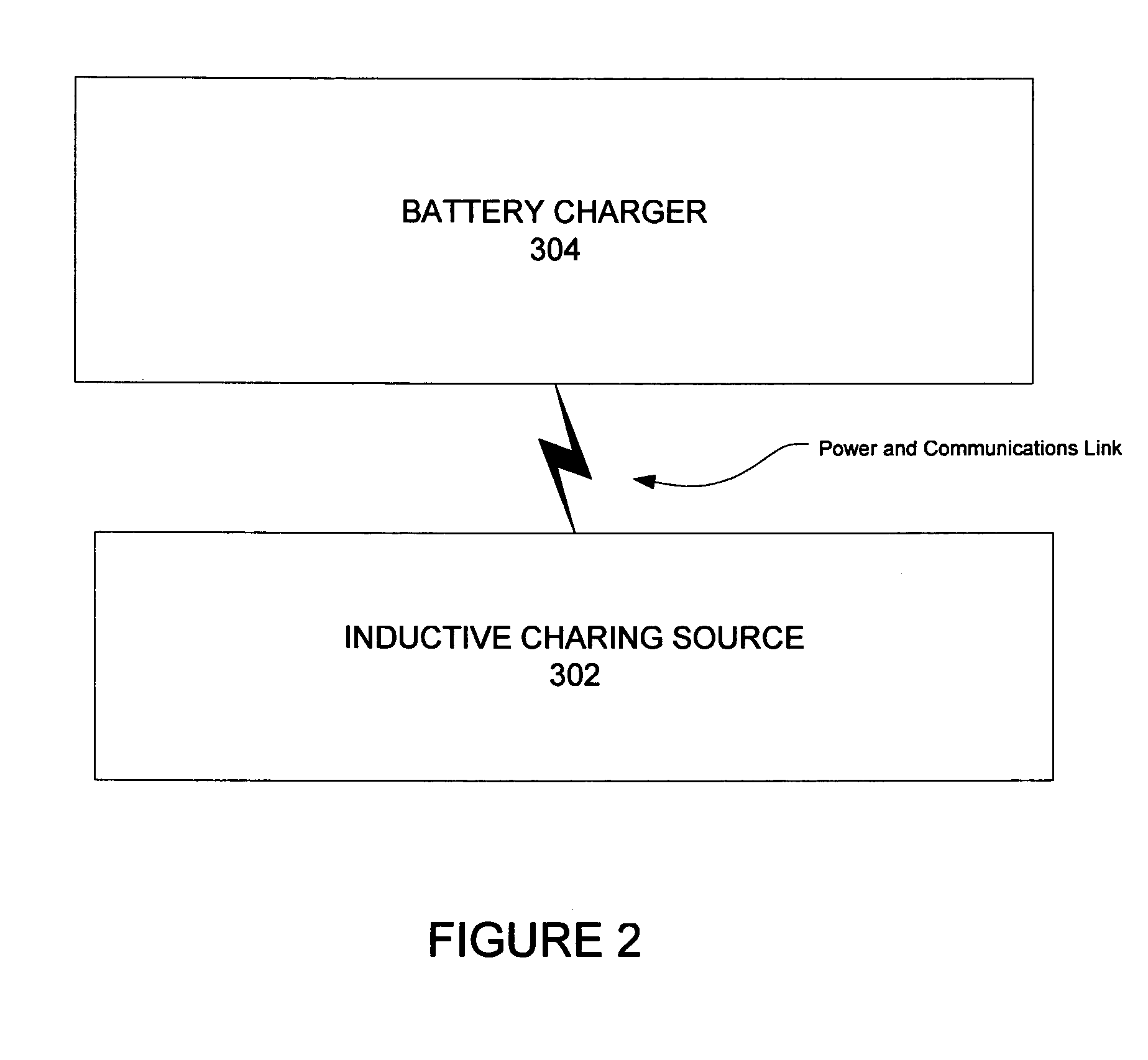
[0021]Aspects of the present invention provide inductive charging arrangements enabling user convenience in wireless power environments for mobile computing and communications devices. An inductive charging system transfers energy by inductively coupling a source coil on a power source to a receiver coil for a battery charger portion. Current flows through the source coil and the resulting magnetic flux induces an alternating current through the magnetic field and across the receiver coil, completing an energy transfer circuit. The source current may be received in the battery charger and converted for charging a battery pack. Aspects of the present invention enable communication between an inductive power source and the battery char...


PUM


Abstract

An inductive charging system transfers energy by inductively coupling a source coil on a power source to a receiver coil for a battery charger. Source current may be received in the battery charger and converted for charging a battery pack. A wireless communication arrangement may also provide for authentication of devices that are allowed by the source to be powered or otherwise charged.

Description

CROSS REFERENCE TO RELATED APPLICATIONS[0001]The present application is related to application Ser. No. 10 / 733,760, entitled “Inductively Charged Battery Pack,” and filed on Dec. 12, 2003; which is related to application Ser. No. 10 / 733,850, entitled “Inductive Power Adapter,” and filed on Dec. 12, 2003, each of which is incorporated by reference herein as to their entireties.FIELD OF THE INVENTION[0002]Aspects of the present invention relate to battery packs that can be coupled to electronic apparatus. More particularly, aspects of the present invention relate to an inductive battery charger for physically coupling and electrically communicating with battery packs and providing electrical energy for charging a battery pack.BACKGROUND OF THE INVENTION[0003]Computer systems have become increasingly popular in modern society. Conventional computer systems, especially computer systems using graphical user interface (GUI) systems, accept user input from a conventional input device, such...

Claims


Application Information

Patent Timeline
Patent Type & Authority Patents(United States)
IPC IPC(8): H02J7/00G06F1/26G06F21/00H02J7/02
CPCG06F1/26G06F21/81H02J7/025G06F2221/2129H02J7/00045H02J50/40H02J50/80H02J50/10
Inventor CALHOON, JOHN CHARLESKEELY, LEROY B.MITCHELL, WILLIAM
Owner MICROSOFT TECH LICENSING LLC
Why Eureka
Try Eureka