
Multifunction vacuum cleaner

a vacuum cleaner and multi-functional technology, applied in the field of vacuum cleaners, can solve the problems of inefficiency of inability to remove the main body portion of general conventional upright vacuum cleaners, and several above-described structures of general upright vacuum cleaners, etc., and achieve compact and economical effects, easy attachment or separation

Inactive Publication Date: 2008-05-27
SAMSUNG GWANGJU ELECTRONICS CO LTD
View PDF12 Cites 90 Cited by
  • Summary
  • Abstract
  • Description
  • Claims
  • Application Information

AI Technical Summary

Benefits of technology

[0015]Another object of the present invention is to provide a multifunction vacuum cleaner of an improved structure, of which the main body of the cleaner is easy to attach to or separate from the frame portion.
[0016]Yet another object of the present invention is to provide a multifunction vacuum cleaner which is compact and economical.
[0024]The connecting groove preferably has a slanted part for easier insertion of the main body into the frame portion. It is preferable that the frame portion comprises wheels on both sides of the bottom thereof, which are disposed for use with the frame portion to permit easier motion of the vacuum cleaner over the area or surface to be cleaned.

Problems solved by technology

However, the above-described structure of a general upright vacuum cleaner has several problems, such as the following.
Therefore, when the area to be cleaned is narrow or has obstacles, such as a projection or a doorsill, conventional upright vacuum cleaners are inefficient to use.
Further, the main body portion of general conventional upright vacuum cleaners is not removable.
As a result, upright vacuum cleaners comprising an integral dust collector are somewhat bulky.
Still further, for cleaning a narrow area or an area having obstacles, a user needs to additionally prepare and have ready a variety of auxiliary brushes or accessories for a vacuum cleaner, or is required to buy a separate small vacuum cleaner, which becomes quite uneconomical.

Method used


Image

  • Multifunction vacuum cleaner
  • Multifunction vacuum cleaner
  • Multifunction vacuum cleaner

Examples


Embodiment Construction

[0034]Hereinafter, preferred embodiments of a cyclone type vacuum cleaner according to the present invention will be described in detail with reference to the accompanying drawings.

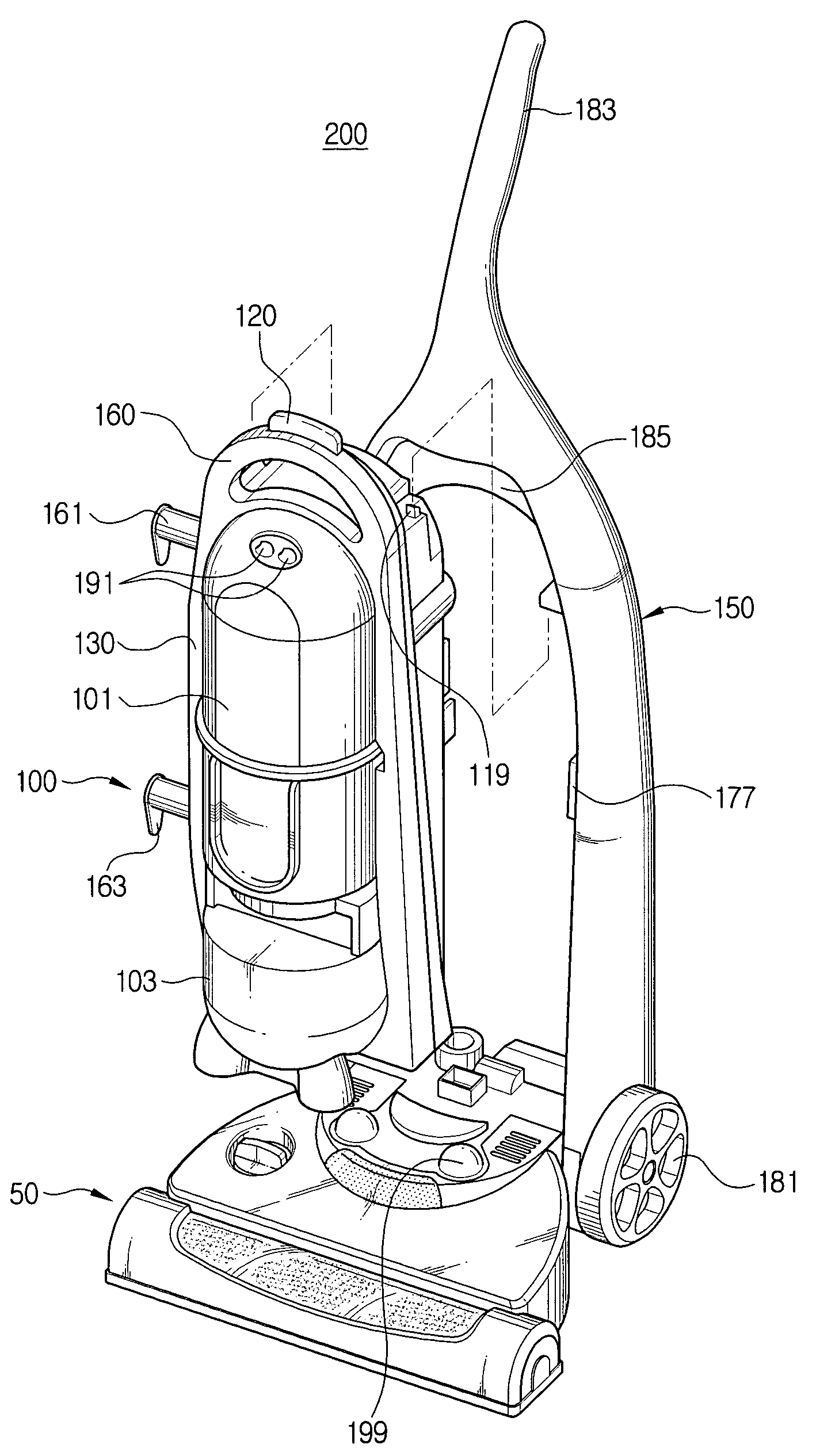
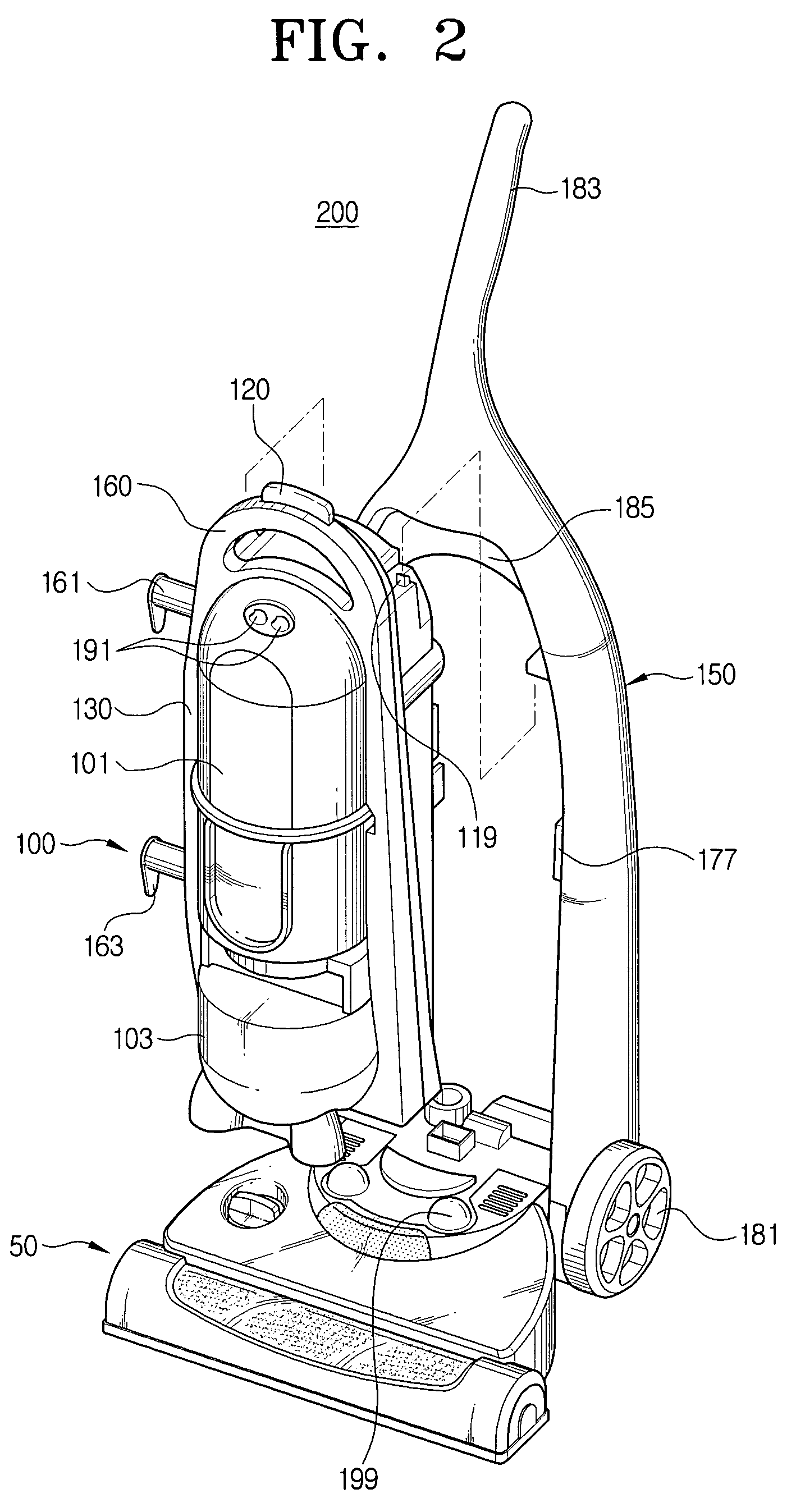
[0035]FIG. 2 is a perspective view showing the structure of a multifunction vacuum cleaner according to a preferred embodiment of the present invention having a main body removable from a frame portion.

[0036]Referring to FIG. 2, the vacuum cleaner comprises a nozzle assembly 50, a main body 100 fluidly communicating with the nozzle assembly 50, and a frame portion 150 which is pivotably connected with the nozzle assembly and capable of pivoting in relation to the nozzle assembly 50. The main body 100 is removably connected within the frame portion 150.

[0037]The nozzle assembly 50 has a suction port (not shown) in a bottom surface thereof for drawing in air and entrained dust therethrough, and a seating support 199 formed on the upper part for mounting of the main body 100 into the frame portion 150 in a s...


PUM


Abstract

A multifunction vacuum cleaner, in which a main body is removably connected to a frame portion, comprises a nozzle assembly for suctioning in an air including dusts or dirt on a cleaning area, a main body having a cyclone dust collector for centrifugally separating the dusts or dirt from the sucked air, a dust receptacle for collecting the separated dusts or dirt, a main body frame having an upper casing and a lower casing, a button operation portion formed on an upper part of the main body frame, and a connecting projection integrally formed with the button operation portion and moving elastically, and a frame portion which is pivotably connected with the nozzle assembly, and having a connecting groove to correspond to the connecting projection. The main body of the vacuum cleaner is removably mounted in the frame portion. As a result, the main body can be conveniently connected with or separate from the frame portion.

Description

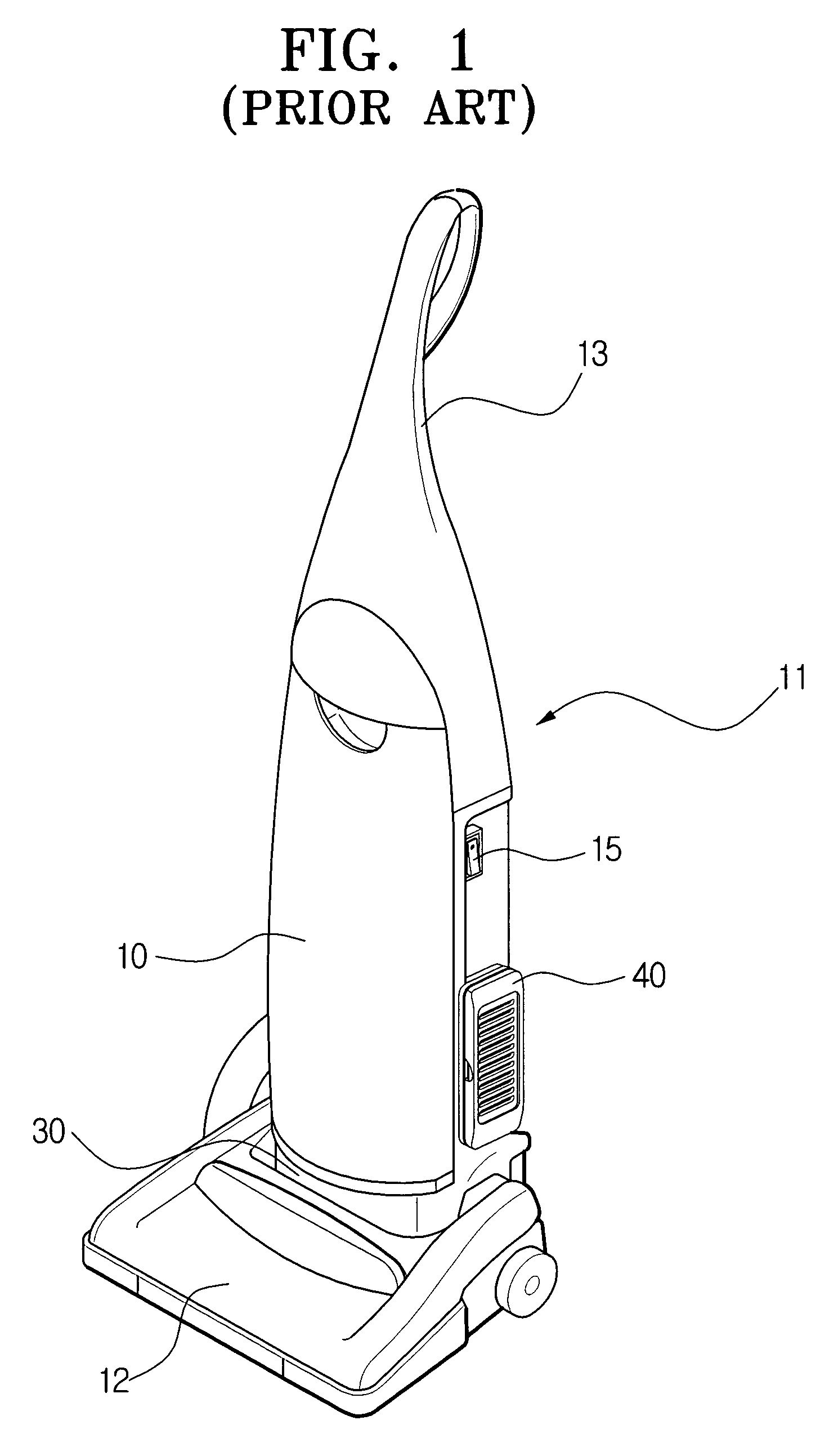
BACKGROUND OF THE INVENTION[0001]1. Field of the Invention[0002]The present invention relates generally to a vacuum cleaner, and more particularly, to a vacuum cleaner for multi purpose use in which the main body of the cleaner is removably mounted in the frame portion.[0003]2. Description of the Related Art[0004]A general upright vacuum cleaner cleans a wide area such as a floor or a carpet, by forcibly suctioning dust and dirt entrained within air that is drawn in by suction force generated inside the main body of the vacuum cleaner.[0005]As shown in FIG. 1, a general conventional vacuum cleaner comprises a nozzle assembly 12 mounted in the bottom part of the main body 11 of the vacuum cleaner to move along an area to be cleaned, such as a floor or carpet. Inside the main body 11, an upper part comprising a dust collecting chamber (not shown) includes a dust bag (not shown in FIG. 1), and a lower part includes a motor driving chamber 30 where a motor is mounted. The dust collectin...

Claims


Application Information

Patent Timeline
IPC IPC(8): A47L5/30A47L9/00A47L5/28A47L9/16
CPCA47L5/225A47L5/28A47L9/1691A47L9/00
Inventor PARK, JUNG-SEONYANG, IL-WON
Owner SAMSUNG GWANGJU ELECTRONICS CO LTD
Learn More