
Automotive steering mechanism housing

a steering mechanism and housing technology, applied in mechanical equipment, transportation and packaging, gearing, etc., can solve the problems of increasing the number of components and complexity of manufacturing operations, prohibitively high cost of single die cast housings, and inconvenient manufacturing, so as to reduce facilitate manufacturing. , the effect of reducing the cost of housings

Inactive Publication Date: 2008-05-27
TEDRIVE HLDG
View PDF13 Cites 0 Cited by
  • Summary
  • Abstract
  • Description
  • Claims
  • Application Information

AI Technical Summary

Benefits of technology

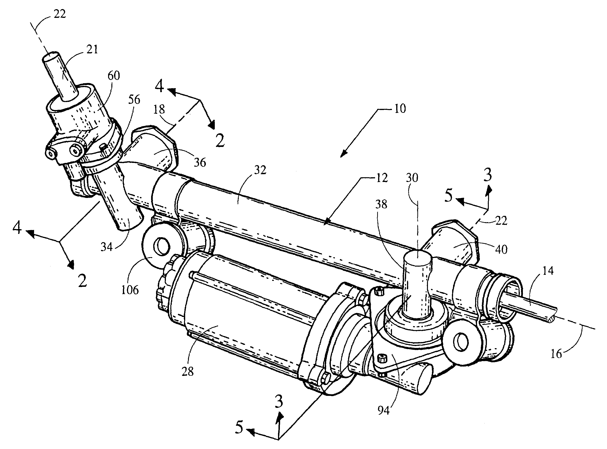
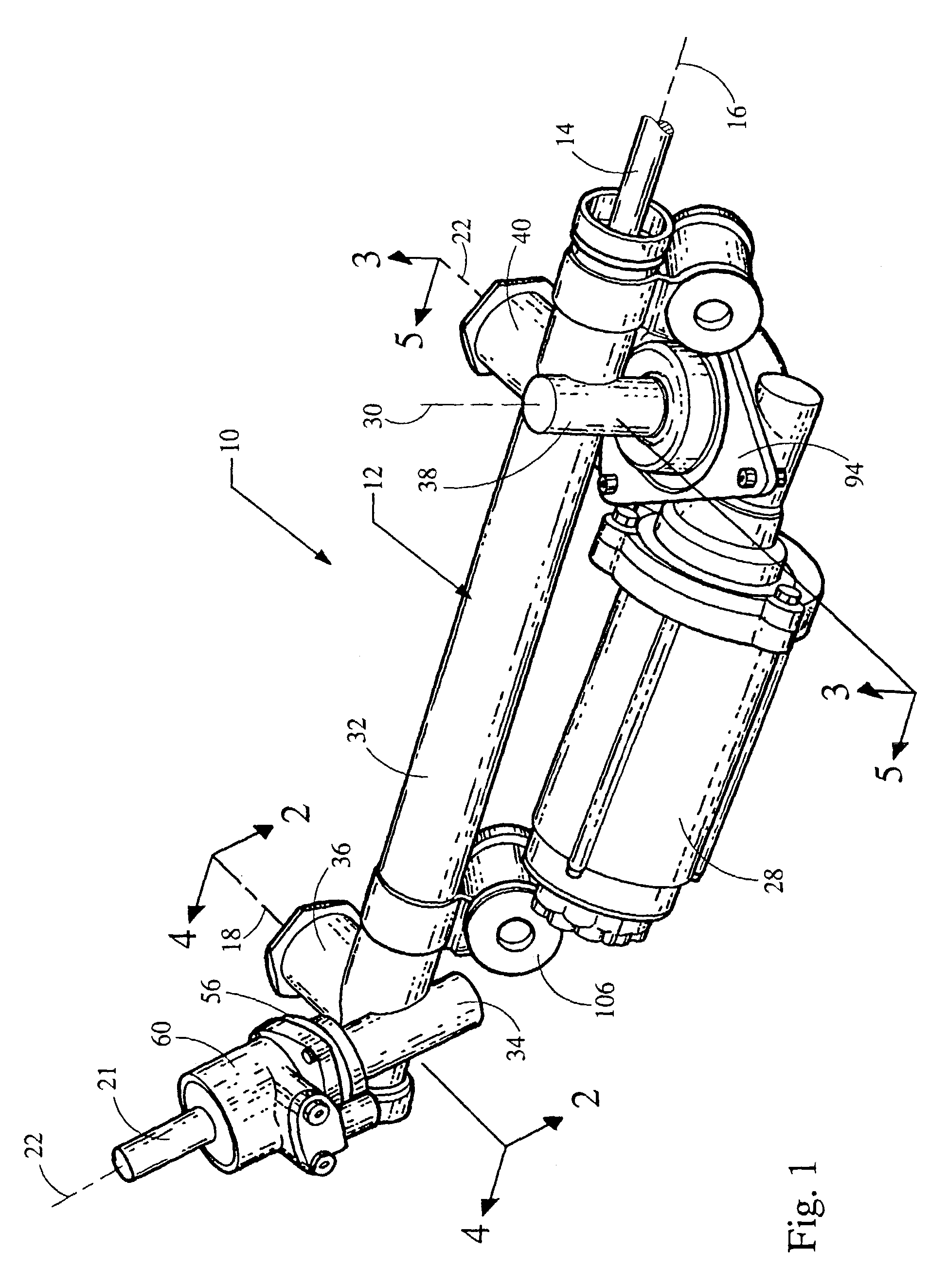
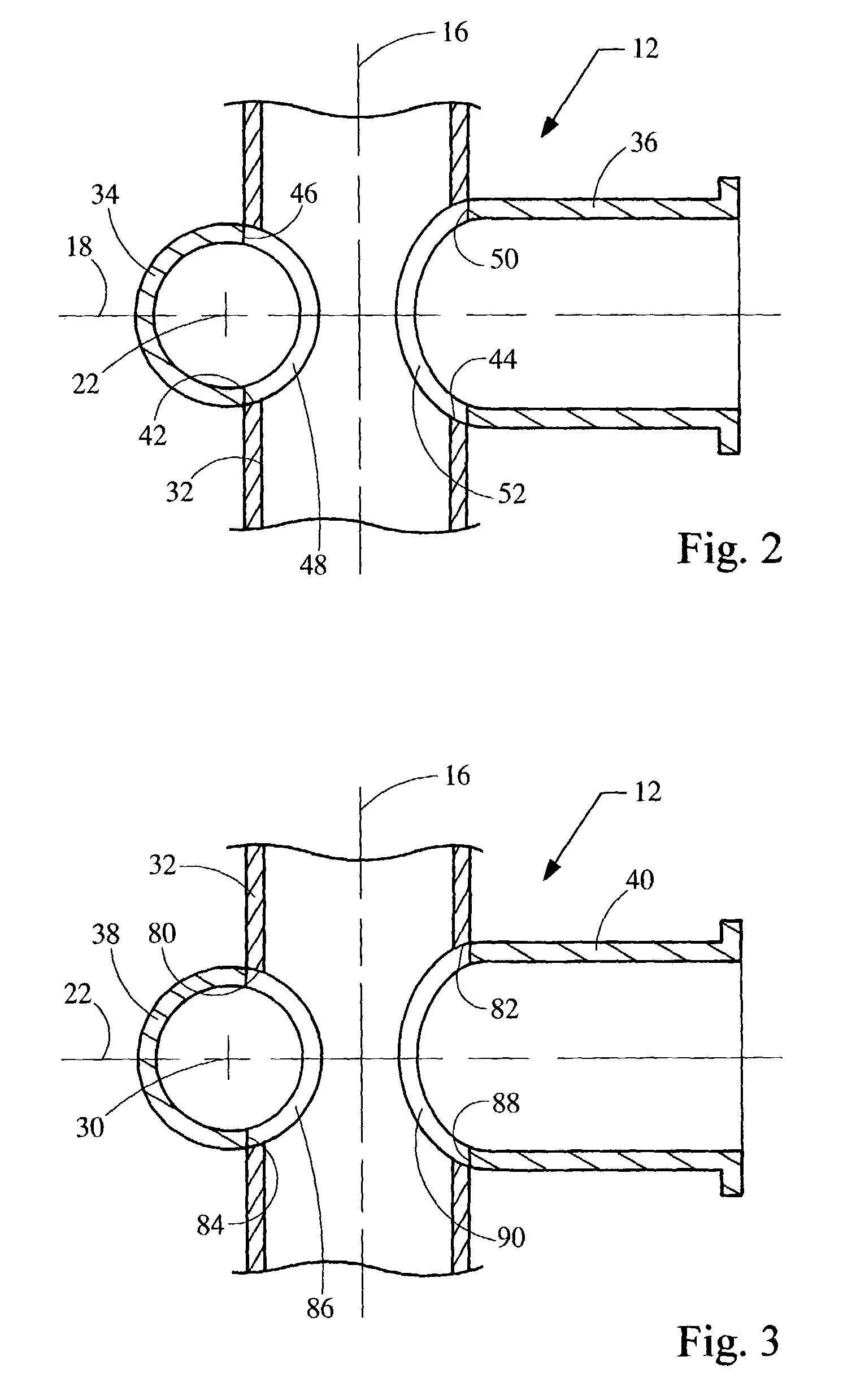
[0007]In a preferred embodiment, this invention provides a composite tubular housing for an automotive steering system that includes a rack, a pinion engaging the rack, and a yoke for biasing the rack against the pinion. The pinion may be either a drive pinion coupled to a steering column and steering wheel or an assist pinion coupled to an electric motor. The composite tubular housing comprises a rack section that is formed of a seamless metal tube symmetrical about a first axis and defines a first opening and a second opening that are symmetrical about a second axis perpendicular to the first axis. The composite tubular housing further comprises a pinion section formed of a seamless metal tube that is symmetrical about a pinion axis that intersects the second axis. The pinion section includes a pinion opening that is symmetrical about the second rack axis and is welded to the rack section about the first opening. The composite tubular housing further includes a yoke section that is formed of a seamless metal tube symmetrical about the second rack axis and includes an open end welded to the rack section about the second opening. Thus, this invention provides a housing that is formed of seamless metal tubing that is welded into a single component and includes sections that contain the rack, pinion and yoke of the automotive steering system. The length of the metal sections, and in particular the length of the rack housing section, may be sized as desired to accommodate the particular steering component. The composite tubular housing of this invention is readily manufactured without requiring sliding coring such as in die casting operations, and so reduces the cost of the housing.
[0008]In one aspect of this invention, a composite tubular housing is provided for an automotive steering system that includes electric power assist steering. The housing includes a rack section formed of a seamless metal tube having a first axis. The rack section includes a first opening and a second opening symmetrical about a second axis, and also a third opening and a fourth opening symmetrical about a third axis that is spaced apart from the second axis. A drive pinion section for receiving a drive pinion is formed of a seamless metal tube having a drive pinion axis perpendicular to the second axis. The drive pinion section includes a drive pinion opening symmetrical about the second axis and is welded to the rack section about the first opening. A drive yoke section is disposed opposite the rack from the drive pinion. The drive yoke section is formed of a seamless metal tube symmetrical about the second rack axis and includes an open end welded to the rack housing about the second opening. In this aspect of the invention, the housing also includes an assist pinion section for receiving an assist pinion, which is formed of a seamless metal tube having an assist pinion axis perpendicular to the third rack axis. The assist pinion housing section includes an assist pinion opening symmetrical about the third axis and is welded to the rack housing about the third opening. An assist yoke section is provided opposite the rack from the assist pinion and is formed of a seamless metal tube symmetrical about the third axis, with an open end welded to the rack housing section about the fourth opening. Therefore, this invention provides a composite tubular housing that is a singular component and includes housing sections for both the drive pinion and the assist pinion, as well as the related yokes, and which further is readily manufactured from seamless metal tubing at reduced cost, particularly in comparison to die cast housings. It is a further advantage of this aspect of the invention that the drive pinion section and the assist pinion section are independent and that the manufacturing process allows the housings to be independently oriented as desired for a particular application.

Problems solved by technology

Extension of the rack coring, and the additional slide coring for the assist pinion, add substantially to the complexity and cost of the die casting, making a singular die cast housing prohibitively expensive.
Thus, dual pinion steering mechanisms for EPAS systems use separate housings for the drive pinion and the assist pinion, which adds to the number of components and complexity of the manufacturing operations.

Method used


Image

  • Automotive steering mechanism housing
  • Automotive steering mechanism housing
  • Automotive steering mechanism housing

Examples


Embodiment Construction

[0015]In accordance with a preferred embodiment of this invention, referring to the Figures, an electronic power assist steering system 10 for an automotive vehicle comprises a composite tubular housing 12. The steering system includes, as major elements, a rack 14 elongated along an axis 16 and operatively coupled to wheels of the vehicle. During operation, the rack is axially displaced in response to a steering command from the operator to vary the orientation of the wheels for steering the vehicle. A drive pinion 20, shown in FIG. 4, engages rack 14 at a location corresponding to a second axis 18 that perpendicularly intersects axis 16. Drive pinion 20 is operatively coupled to a steering column 21 and is rotatable about a drive pinion axis 22. Steering column 21 is operatively coupled to a steering wheel, which is turned by the operator to rotate the steering column and thereby rotate the drive pinion, axially displacing rack 14. In this preferred embodiment, system 10 includes ...


PUM


Abstract

A composite tubular housing for an automotive steering system, preferably an electronic power assist steering system, is formed of seamless metal tube section welded into an integral component. The housing includes a rack section and a pinion section having an opening that is welded to the rack section. A yoke section is formed of a tube having an end that is welded to the rack section opposite the pinion section. The pinion section may contain a drive pinion coupled to a steering wheel of the vehicle. The housing may also include sections for an assist pinion coupled to an electric motor, and a yoke which are attached to the rack section apart from the drive pinion.

Description

TECHNICAL FIELD OF THE INVENTION[0001]This invention relates to a rack and pinion steering mechanism for an automotive vehicle. More particularly, this invention relates to a composite tubular housing for such steering mechanism.BACKGROUND OF THE INVENTION[0002]A typical steering system for an automotive vehicle comprises a rack and pinion mechanism. The rack is operatively connected to wheels of the vehicle and includes teeth. The pinion, also referred to as the drive pinion, engages the rack teeth and is operatively coupled to the steering wheel. A yoke assembly is disposed opposite the pinion to bias the rack against the pinion and prevent slippage. During operation, an operator inputs a steering command by turning the steering wheel to rotate the pinion, which in turn laterally displaces the rack to change the orientation of the wheels.[0003]To reduce the steering force needed by the operator to turn the steering wheel, the vehicle may be equipped with an electric power assist s...

Claims


Application Information

Patent Timeline
Patent Type & Authority Patents(United States)
IPC IPC(8): F16H35/00B60D1/02B62D3/12B62D5/04
CPCB62D3/126B62D5/0424
Inventor BOWLING, BRUCE ALLENMCELMEEL, JR., EDWARD FRANCISPALAKODATI, SUNIL
Owner TEDRIVE HLDG
Learn More