Supercharge Your Innovation With Domain-Expert AI Agents!

Camshaft adjuster for an internal combustion engine and a method for operating a camshaft adjuster

a technology of camshaft adjuster and internal combustion engine, which is applied in the direction of valve details, valve arrangements, valve drives, etc., can solve the problems of advantageously low wear of the coupling mechanism, and achieve the effects of rapid release of the clutch, fast braking, and virtually free wear

Inactive Publication Date: 2008-05-27
DAIMLER AG
View PDF14 Cites 0 Cited by
  • Summary
  • Abstract
  • Description
  • Claims
  • Application Information

AI Technical Summary

Benefits of technology

The invention relates to a camshaft adjustment mechanism for an internal combustion engine. The mechanism includes a gear mechanism, an input drive element, a camshaft, and a brake mechanism. A coupling mechanism is provided for locking the adjustment mechanism in a particular phase position. The mechanism allows for quick and easy adjustment of the camshaft position, with low wear and low brake loss. The brake mechanism can be actuated in a contact-free manner, and the gear mechanism can be self-locking or hysteresis braking. The mechanism is compact and easily controllable, and can be used in a variety of engine configurations.

Problems solved by technology

Furthermore, the wear of the coupling mechanism is advantageously low.

Method used


Image

  • Camshaft adjuster for an internal combustion engine and a method for operating a camshaft adjuster
  • Camshaft adjuster for an internal combustion engine and a method for operating a camshaft adjuster
  • Camshaft adjuster for an internal combustion engine and a method for operating a camshaft adjuster

Examples


Embodiment Construction

[0025]In the figures, identical or corresponding elements are descended by the same reference numbers.

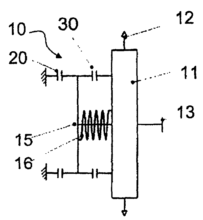
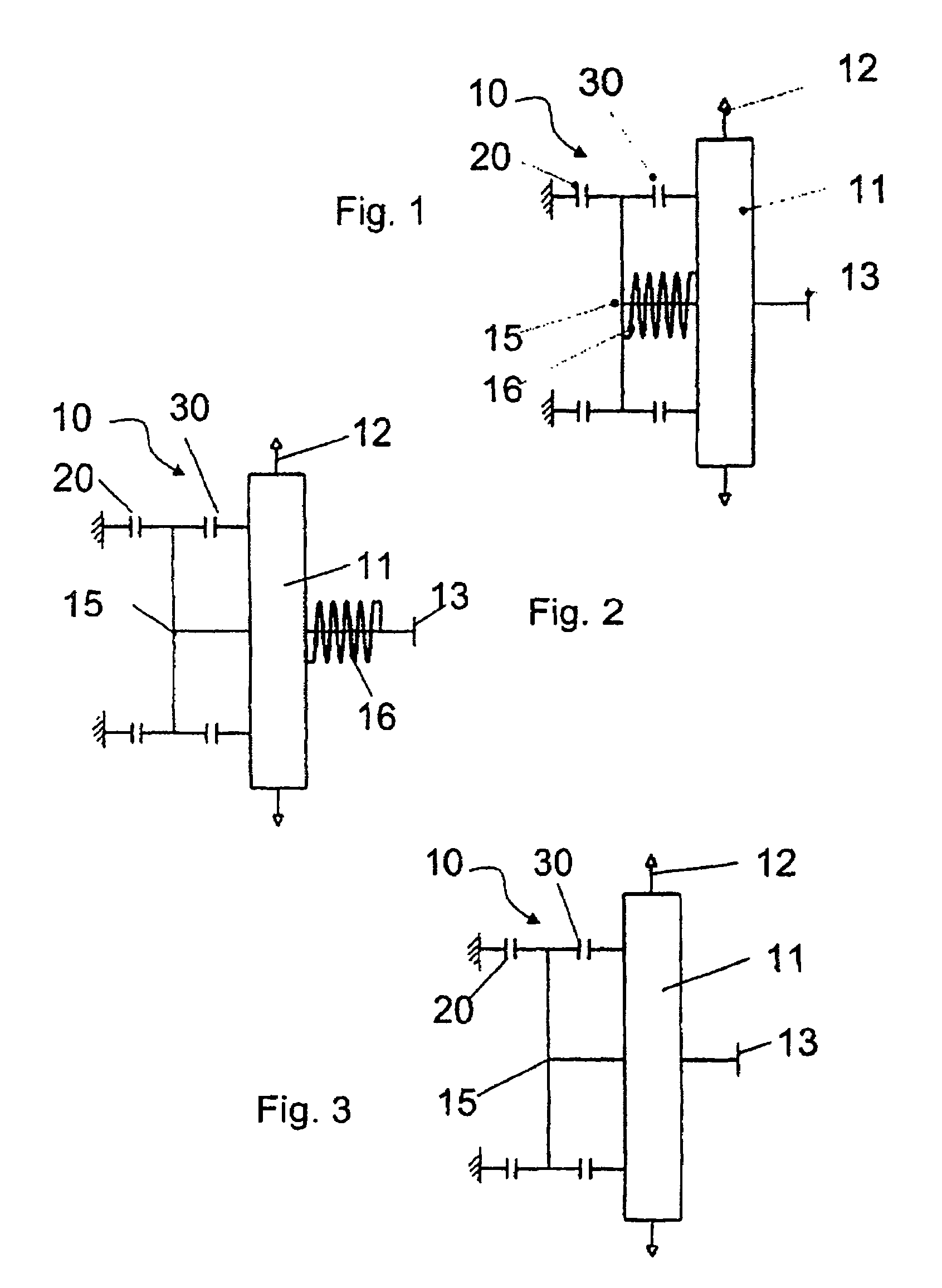
[0026]FIGS. 1 to 3 show schematically a camshaft adjustment mechanism 10 according to the invention. The adjustment mechanism 10 in the figures comprises a preferred gear mechanism 11 with drive element 12, for example a chain wheel, which can be driven via a chain (not illustrated) by a crankshaft of an internal combustion engine (not illustrated). An output element 13 is connected to the camshaft.

[0027]To simplify the control, the gear mechanism 11 can be self-locking (FIGS. 1 and 2), so that changing torques of the camshaft cannot reach the adjustment input 15. An adjustment of the phase position of the camshaft takes place by the adjustment input 15 being braked by means of a brake mechanism 20 for adjustment in a first direction. An adjustment in a direction opposed to the first direction takes place by means of an adjustment spring 16. FIG. 1 shows the adjustment spring 16 bet...


PUM


Abstract

In a camshaft adjuster for an internal combustion engine including a gear mechanism, an input drive element, a camshaft as an output element, and a brake mechanism for braking an adjustment input for the adjustment of a phase position of the camshaft, a coupling mechanism is provided for locking the adjustment mechanism at a particular phase position while the brake mechanism is inactivated.

Description

[0001]This is a Continuation-In-Part application of pending International patent Application PCT / EP2005 / 004626 filed Apr. 29, 2003 and claiming the priority of German patent application 10 2004 023 548.1 filed 13 May 2004.BACKGROUND OF THE INVENTION[0002]The invention relates to an adjustment mechanism of a camshaft, to a device for use in an adjustment mechanism and to a method for operating an adjustment mechanism.[0003]In order to change the phase position of a camshaft, hydraulic blade-type adjustors are known, but their adjustment speed and adjustment angle range are small. At low rotational speeds and at a low oil pressure, an adjustment is impossible. Passive electric adjustment mechanisms for camshafts permitting sufficiently high adjustment speeds and large adjustment angles have therefore already been proposed. DE 102 47 650 A1 discloses an electric adjustment mechanism of a camshaft which comprises a brake mechanism, a lever mechanism as the gear mechanism, and an adjustm...

Claims


Application Information

Patent Timeline
Patent Type & Authority Patents(United States)
IPC IPC(8): F01L1/34F01L1/344F01L1/352
CPCF01L1/352F01L2820/031
Inventor MEINTSCHEL, JENS
Owner DAIMLER AG
Features
  • R&D
  • Intellectual Property
  • Life Sciences
  • Materials
  • Tech Scout
  • Unparalleled Data Quality
  • Higher Quality Content
  • 60% Fewer Hallucinations
Learn More