Linear position sensor for downhole tools and method of use

a position sensor and downhole technology, applied in the field of downhole tools, can solve the problems of inaccurate pressure transducer, potentiometers are known to be susceptible to mechanical wear and temperature drift, and the potentiometer is known to suffer from various drawbacks, etc., to achieve accurate and reliable measurements, low mass, and low cost

Inactive Publication Date: 2008-05-27
SCHLUMBERGER TECH CORP
View PDF68 Cites 50 Cited by
  • Summary
  • Abstract
  • Description
  • Claims
  • Application Information

AI Technical Summary

Benefits of technology

[0008]Exemplary embodiments of the present invention may advantageously provide several technical advantages. For example, sensor embodiments in accordance with the present invention are non-contact and therefore not typically subject to mechanical wear. Moreover, embodiments of this inve...

Problems solved by technology

While prior art sensors are known to be serviceable, such as for measuring blade and/or piston position, they are also known to suffer from various drawbacks.
For example, potentiometers are known to be susceptible to mechanical wear and temperature drift due to the analog sensing and outputting mechanism utilized.
Pressure transducers are known to be inaccurate for position sensin...

Method used


Image

  • Linear position sensor for downhole tools and method of use
  • Linear position sensor for downhole tools and method of use
  • Linear position sensor for downhole tools and method of use

Examples


embodiment 400

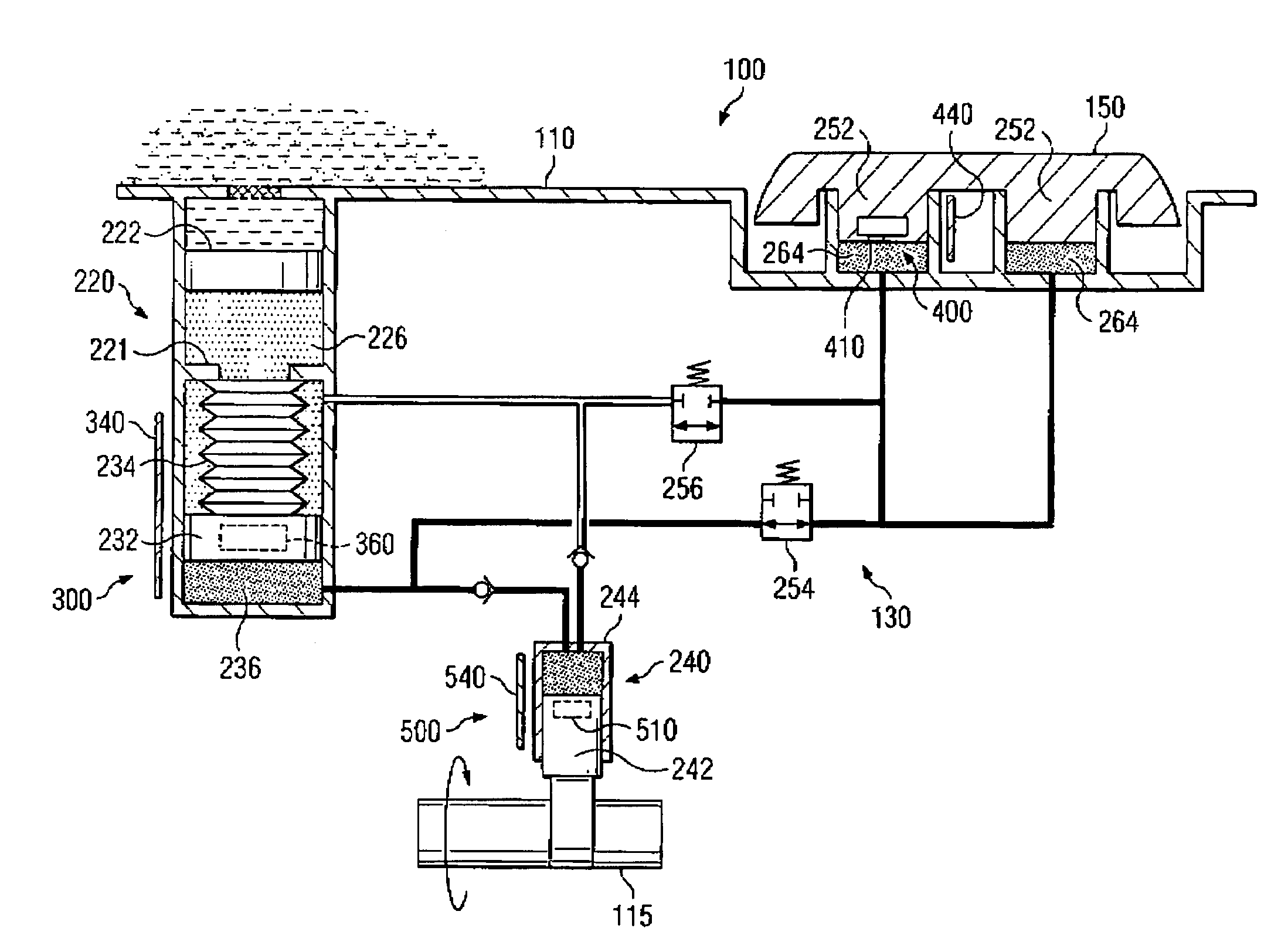
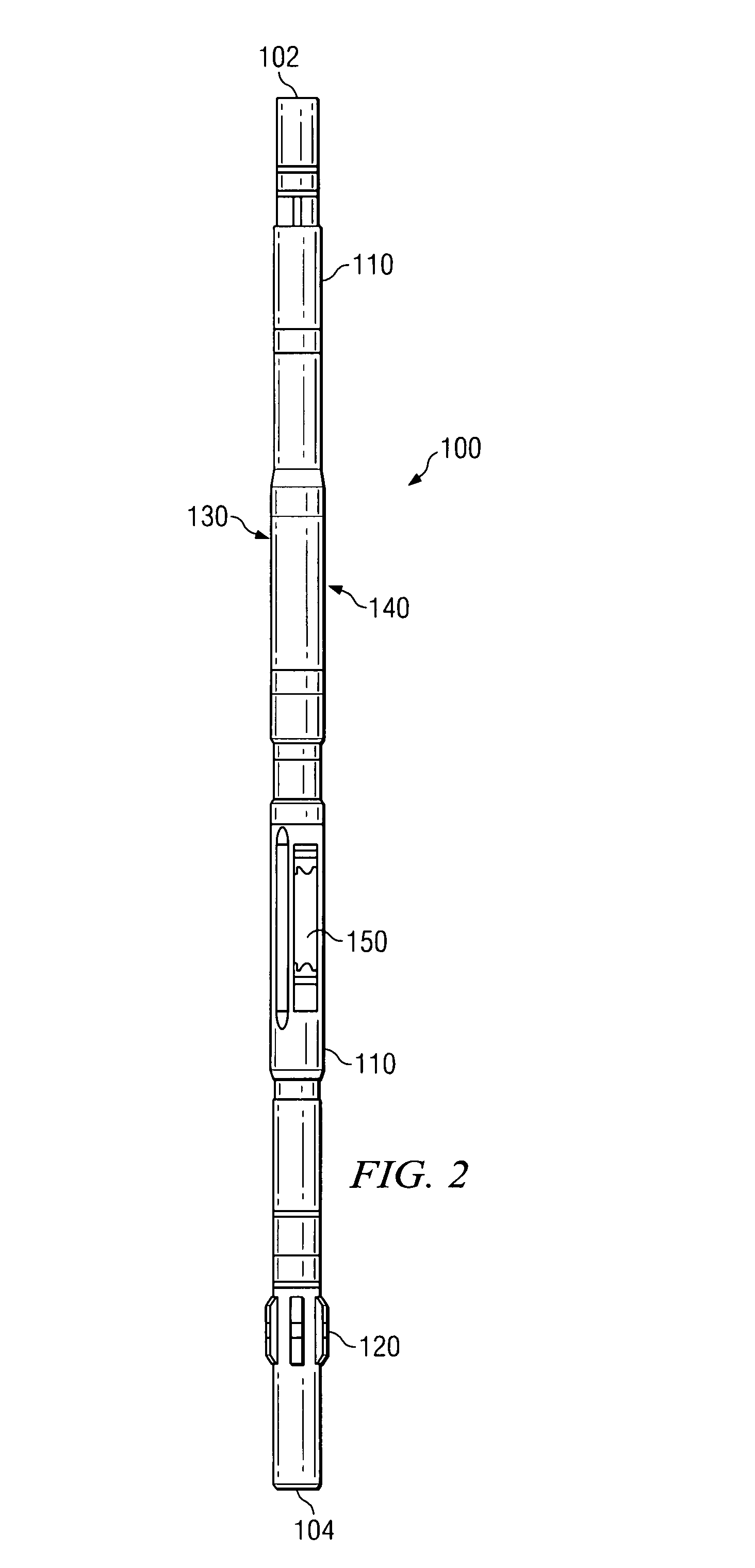
[0038]With reference now to FIG. 5, sensor embodiment 400 is shown in greater detail. As described above, position sensor 400 is disposed to measure the position of blade 150 (FIGS. 2 and 3). As shown on FIG. 5, blade 150 is in its fully retracted position within housing 110. In the embodiment shown, magnet assembly 410 is fixed to an inner surface of the blade 150 (inside piston 252 as shown on FIG. 3). As hydraulic fluid is pumped into chamber 264, the blade extends outward from a longitudinal axis of the tool in the direction of arrow 405. Magnetic sensor array 440 is deployed within the blade housing in close enough proximity to magnet assembly 410 such that at least one of the sensors 450A-H on sensor array 440 is in sensory range of magnetic flux emanating from the assembly 410. In the exemplary embodiment shown on FIG. 5, magnet assembly 410 is substantially similar to magnet assembly 360′, although an assembly similar to magnet assembly 360 may also be equivalently utilized....

embodiment 500

[0040]Turning now to FIG. 6, sensor embodiment 500 is shown in greater detail. Position sensor 500 is disposed to measure the axial position of piston 242 in housing 244. As shown on FIGS. 3 and 6, rotation of shaft 115 causes piston 242 to reciprocate in housing 244 (e.g., due to a cam on the shaft). Magnetic sensor array 540 is deployed on an outer surface of housing 244 in close enough proximity to magnet assembly 510 such that at least one of the sensors 550A-I is in sensory range of magnetic flux emanating from the assembly 510. In the exemplary embodiment shown on FIG. 6, magnet assembly 510 is substantially similar to magnet assembly 360′, although an assembly similar to magnet assembly 360 may also be equivalently utilized. Sensors 550A-I may be deployed having substantially any suitable alignment (e.g., parallel or perpendicular to array 540).

[0041]With continued reference to FIGS. 3 and 6, it will be appreciated that sensor embodiment 500 is disposed to measure several too...


PUM


Abstract

Aspects of this invention include a downhole tool having first and second members disposed to translate substantially linearly with respect to one another. A magnet is deployed on the first member and a plurality of magnetic field sensors is deployed on the second member. The magnetic field sensors are spaced in a direction substantially parallel with a direction of translation between the first and second members. The tool typically further includes a controller disposed to determine a linear position of the first and second members with respect to one another from magnetic flux measurements made at the magnetic field sensors. Exemplary position sensor embodiments of the present invention are non-contact and therefore are not typically subject to mechanical wear. Embodiments of the invention therefore tend to advantageously provide for accurate and reliable linear position measurements.

Description

RELATED APPLICATIONS[0001]None.FIELD OF THE INVENTION[0002]The present invention relates generally to downhole tools, for example, including directional drilling tools having one or more steering blades. More particularly, embodiments of this invention relate to a sensor apparatus and a method for determining the linear position of various components, such as steering blades and / or hydraulic pistons used in downhole tools.BACKGROUND OF THE INVENTION[0003]Position sensing tools have several important applications in downhole tools used in subterranean drilling. For example, many drilling applications require directional drilling tools to control the lateral drilling direction. Such steering tools commonly include a plurality of force application members (also referred to herein as blades) that may be independently extended out from and retracted into a housing. The blades are disposed to extend outward from the housing into contact with the borehole wall and to thereby displace the h...

Claims


Application Information

Patent Timeline
IPC IPC(8): E21B47/02
CPCE21B7/06E21B17/1014E21B47/024G01D5/145
Inventor SUGIURA, JUNICHI
Owner SCHLUMBERGER TECH CORP
Why Eureka
Try Eureka