Particle beam therapeutic apparatus

a technology of particle beam and beam beam, which is applied in the direction of optical radiation measurement, machines/engines, nuclear elements, etc., can solve the problems of inability to ensure the uniformity of dose distribution in each the constraint in the operation period of the accelerator, and the inability to shorten the supply time of the particle beam

Active Publication Date: 2008-05-27
MITSUBISHI ELECTRIC CORP
View PDF13 Cites 102 Cited by
  • Summary
  • Abstract
  • Description
  • Claims
  • Application Information

AI Technical Summary

Benefits of technology

[0018]The particle beam therapeutic apparatus as constructed above according to the present invention provides the following remarkable advantageous effects. That is, irradiation is repeatedly carried out in units of the spiral period, so the possibility of irradiation being interrupted during the spiral period can be eliminated, as a result of which even if the dose rate is raised, the uniformity of dose distribution can be ensured in a reliable manner, thus making it possible to shorten the irradiation time. In addition, constraints on the operation period of an accelerator can be alleviated.

Problems solved by technology

In this manner, the conventional spiral wobbler method involves a problem that it is necessary to perform irradiation in such a manner that a lot of spiral loci are overlapped each other.
In addition, each spiral phase φ is uniquely decided by the spiral period TS and the wobbler angular velocity ω, so the wobbler angular velocity ω capable of ensuring the uniformity of the dose distribution when the spiral period TS is changed is limited, thus posing a problem that a constraint arises in the selection of the spiral period TS and the wobbler angular velocity ω.
However, when the time to supply the particle beam is hundreds of milliseconds, the supply of the particle beam is interrupted at a time during one spiral period, thus posing a problem that there is no guarantee for which the uniformity of dose distribution in each operation period of the accelerator is ensured.
Accordingly, there is another problem that when it is intended to prevent the interruption of the supply of the particle beam during the spiral period by increasing the time to supply the particle beam, there arises a constraint in the operation period of the accelerator such as the inability to shorten the supply time of the particle beam.
Further, in a respiration synchronized operation in which the irradiation of the particle beam is turned on and off according to respiration when irradiation is performed on internal organs that are caused to move or deform in accordance with the respiration or breathing of a patient, the supply of the particle beam is interrupted during the spiral period TS, thus causing a problem that there is no guarantee for which the uniformity of the dose distribution is ensured.
Furthermore, when the spiral wobbler method is applied to a layer-stacking conformal irradiation method in which irradiation on a patient is performed by dividing an exposure or irradiation area of the patient into a plurality of subareas or layers in the direction of depth thereof, a planned dose for each of the subareas or layers thus divided becomes smaller, so the number or frequency of spiral periods (hereinafter also referred to as a spiral number or frequency) is decreased, resulting in a problem that a spiral frequency required to ensure the uniformity of dose distribution can not be reached.
Besides, since the number or frequency of spiral periods is necessary to be equal to or more than a predetermined number of times, there is a further problem that when the dose rate is raised, the number or frequency of spiral periods required falls below the predetermined frequency, so the uniformity of dose distribution can not be ensured, and it is necessary to increase the exposure or irradiation time.

Method used


Image

  • Particle beam therapeutic apparatus
  • Particle beam therapeutic apparatus
  • Particle beam therapeutic apparatus

Examples


embodiment 1

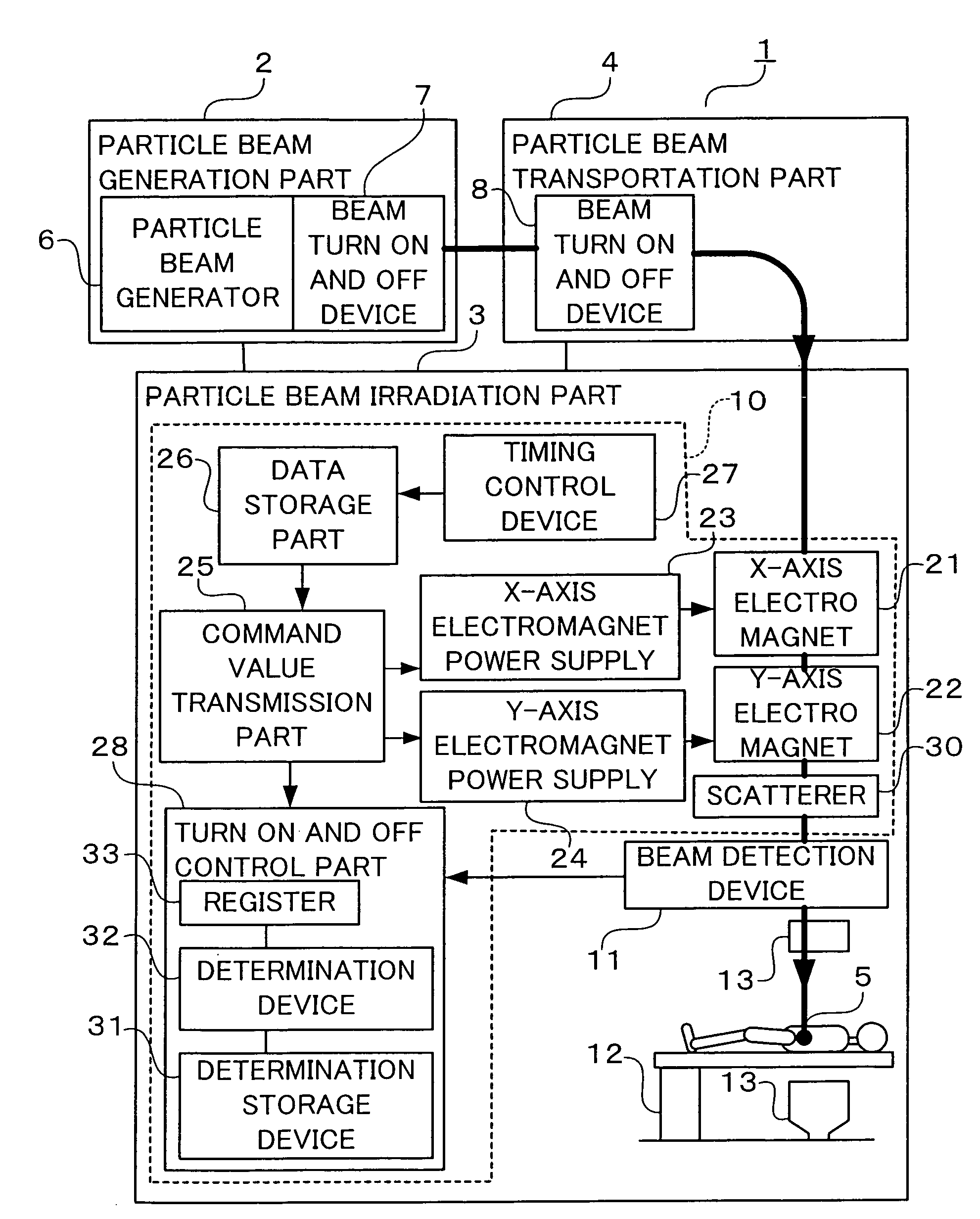
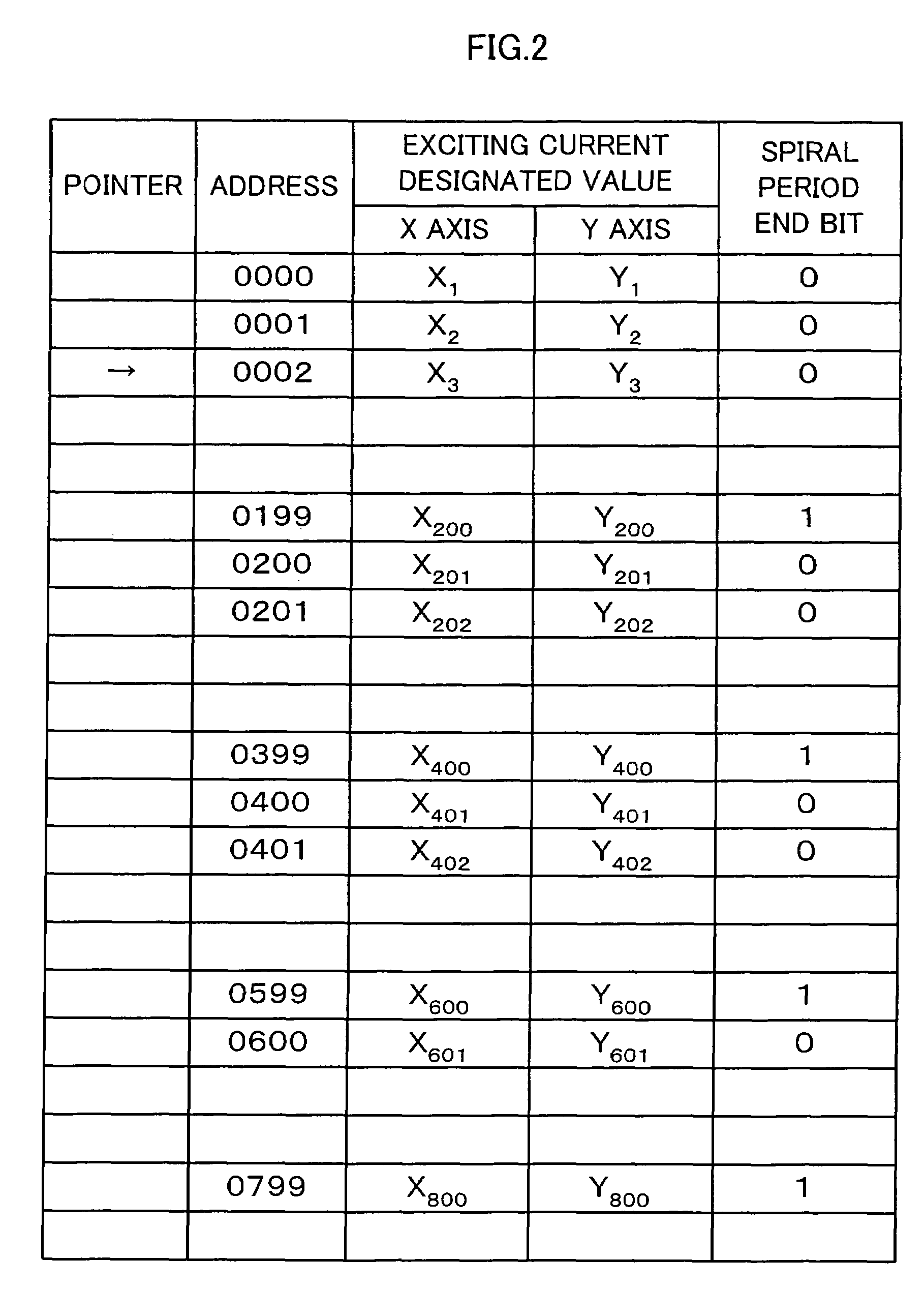
[0052]FIG. 1 is a block diagram that shows a particle beam therapeutic apparatus according to a first embodiment of the present invention. FIG. 2 is a view that shows the data structure of a data table in a data storage part according to the first embodiment of the present invention, and FIG. 3 is a block diagram of a beam detection device according to the first embodiment of the present invention.

[0053]As shown in FIG. 1, the particle beam therapeutic apparatus, generally designated at reference numeral 1, according to the first embodiment of the present invention includes a particle beam generation part 2 for generating a particle beam, a particle beam irradiation part 3 for irradiating the particle beam to a target region (diseased part) 5 of a patient, and a particle beam transportation part 4 for transporting the particle beam generated by the particle beam generation part 2 to the particle beam irradiation part 3.

[0054]The particle beam generation part 2 includes a particle be...

embodiment 2

[0079]FIG. 4 is a block diagram of a turn on and off control part in a particle beam therapeutic apparatus according to a second embodiment of the present invention. FIG. 5 shows the data structure of a data table in the data storage part of the particle beam therapeutic apparatus according to the second embodiment of the present invention. In the above-mentioned first embodiment, the particle beam is turned on and off by reading a spiral period end bit stored in the data storage part 26 and inputting a pulse in the form of a spiral period end signal to the register 33, but in the second embodiment, the clock signal from the timing control device 27 is counted, and the count value thus obtained is compared with the number of divisions of the spiral period stored beforehand in the determination storage device 31, so that when the count value becomes equal to the number of divisions of the spiral period, the beam is turned on and off by sending a pulse in the form of a spiral period e...

embodiment 3

[0082]FIG. 6 is a block diagram of a turn on and off control part in a particle beam therapeutic apparatus according to a third embodiment of the present invention. The turn on and off control part 28C according to this third embodiment is different from the turn on and off control part 28 of the above-mentioned first embodiment in the addition of an immediate beam interruption function, but the other construction of this third embodiment is similar to the first embodiment, and hence like components or parts are identified by like symbols while omitting a detailed explanation thereof. In the turn on and off control part 28C according to the third embodiment, as shown in FIG. 6, an immediate beam interruption signal, which becomes a “LOW” level when the exposure dose from the determination device 32 reaches the planned dose and a “HIGH” level at the other times, is input to an AND circuit 43.

[0083]Also, the immediate beam interruption signal and a Q output of the register 33 are inpu...


PUM


Abstract

A particle beam therapeutic apparatus can ensure the uniformity of dose distribution by overlapping the desired loci of the irradiation of a particle beam a reduced number of times. A flow of a particle beam transported so as to be irradiated to a diseased part is caused to deflect in two mutually orthogonal directions perpendicular to the direction of travel of the particle beam. The irradiation position of the particle beam is scanned, upon each period, in a manner to return to a position of irradiation located at the start of the period, whereby a plurality of loci drawn within one period are overlapped with one another thereby to irradiate a desired planned dose to the diseased part. The particle beam can be interrupted only at the end of the period.

Description

BACKGROUND OF THE INVENTION[0001]1. Field of the Invention[0002]The present invention relates to a particle beam therapeutic apparatus capable of irradiating a planned dose by repeating the irradiation of a particle beam onto a diseased part.[0003]2. Description of the Related Art[0004]As a process of forming the irradiation field of a particle beam in a conventional particle beam therapeutic apparatus, there have been known a single painting method of performing irradiation over an entire diseased part by moving the position of irradiation of a particle beam each time a desired planned dose at a desired position is reached (see, for example, a first patent document: Japanese patent application laid-open No. 2002-191709) and a repainting method of irradiating a desired planned dose by scanning the position of irradiation of a particle beam in an amount of dose equal to one severalth of a desired planned dose so as to trace a predetermined track or locus with respect to a target area...

Claims


Application Information

Patent Timeline
Patent Type & Authority Patents(United States)
IPC IPC(8): A61N5/00G21G5/00
CPCA61N5/10A61N5/1037A61N2005/1074A61N2005/1087A61N5/1044
Inventor HARADA, HISASHI
Owner MITSUBISHI ELECTRIC CORP
Why Eureka
Try Eureka