Chevron-free FLC device

Inactive Publication Date: 2008-05-27
CITIZEN FINETECH MIYOTA CO LTD
View PDF7 Cites 2 Cited by
  • Summary
  • Abstract
  • Description
  • Claims
  • Application Information

AI Technical Summary

Benefits of technology

[0016]In still another aspect of the invention, a method for preventing formation of chevron structures in an optical device including a ferroelectric liquid crystal material is disclosed. Accordingly, a first and a second substrate are provided. A first alignment treatment is applied to a surface of the first substrate, the first alignment treatment being intended to induce an orientation of at least a portion of the ferroelectric liquid crystal material along a first alignment direction with a first pretilt angle α1 with respect to a plane parallel to the first substrate. A second alignment treatment is applied to a surface of the second substrate, the second alignment treatment being intended to induce an orientation of at least another portion of the electric liquid crystal material along a second alignment direction with a second pretilt angle α2 with

Problems solved by technology

One such drawback is the fact that the device can only be in one of two optical states.
Unlike nematic liquid crystal (NLC) devices, which is capable of analog operation by generating a continuum of optical states between a minimum and a maximum state according to the magnitude of the electric field applied across the NLC material, SSFLC devices are limited to binary operation in which one of two optical states is generated according to whether a positive or negative magnitude electric field is applied across the FLC material.
Since molecular positions between positions A and B are not stable, optical states between the two stable states are not controllably accessible in a conventional SSFLC device.
This inflexibility can be problematic especially in applications in which analog operation is desired.
Still another problem seen in the conventional SSFLC device is the presence of chevron structures.
Due to conservation of mass and the structural boundary conditions, the shrinkage of the smectic layers results in the formation of chevron structures.
Consequently, the presence of chevron structures gives rise to nonuniformity in the optical state produced by the device as a whole.
The use of the AC voltage pretreatment adds an extra step to the manufacturing process of the SSFLC device, thus lead to additional costs associ

Method used


Image

  • Chevron-free FLC device
  • Chevron-free FLC device
  • Chevron-free FLC device

Examples


Example

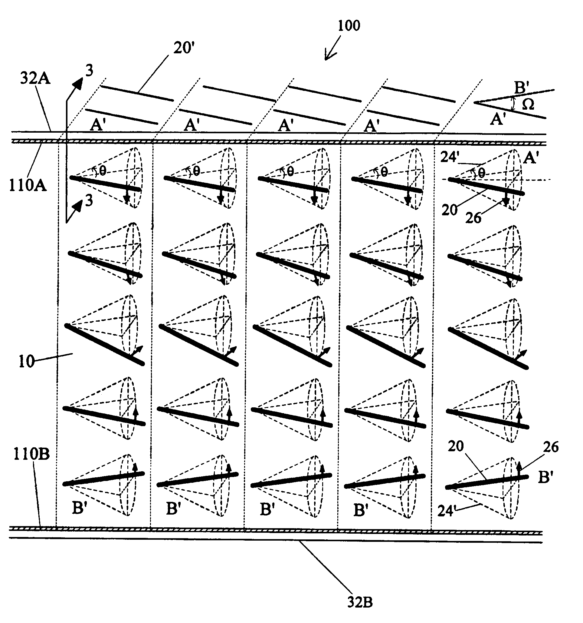
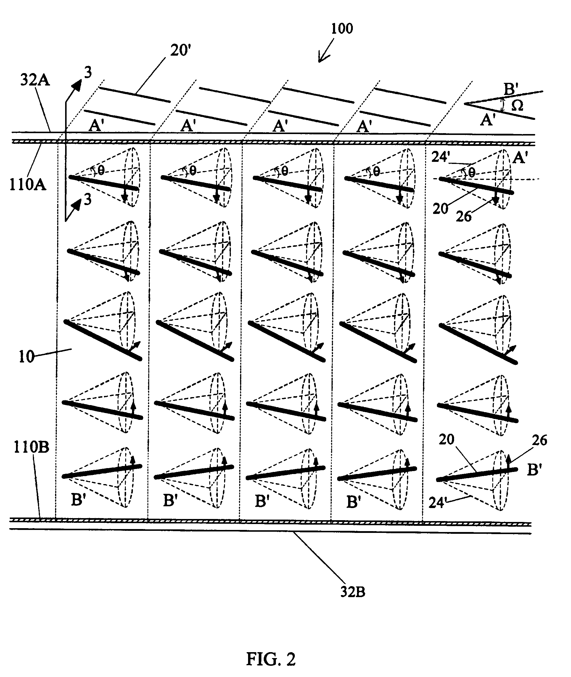
[0024]Attention is now directed to FIG. 2, which illustrates one embodiment of an FLC device, generally indicated by the reference number 100. FLC device 100 includes FLC material 10 confined between a top substrate 32A and a bottom substrate 32B. FLC device 100 also includes an alignment treatment 110A on the inner surface of top substrate 32A and an alignment treatment 110B on the inner surface of bottom substrate 32B. Alignment treatment 110A is designed to induce a predetermined molecular alignment of the portion of the FLC molecules which are located near the top substrate. Alignment treatment 110B is designed to induce a different, predetermined molecular alignment of the portion of the FLC molecules which are located near the bottom substrate. Alignment treatment 110A induces a molecular alignment such that the projection onto top substrate 32A of the director of an FLC molecule located immediately adjacent to top substrate 32A is oriented in a direction A′ as shown in FIG. 2...


PUM

PropertyMeasurementUnit
Angleaaaaaaaaaa
Angleaaaaaaaaaa
Cell angleaaaaaaaaaa

Abstract

An optical device includes a ferroelectric liquid crystal material. This optical device has a first and a second substrate. A first alignment treatment is applied to a surface of the first substrate, the first alignment treatment being intended to induce an orientation of at least a portion of the ferroelectric liquid crystal material along a first alignment direction with a first pretilt angle α1 with respect to a plane parallel to the first substrate. A second alignment treatment is applied to a surface of the second substrate, the second alignment treatment being intended to induce an orientation of at least another portion of the ferroelectric liquid crystal material along a second alignment direction with a second pretilt angle α2 with respect to a plane parallel to the second substrate. The optical device further includes an arrangement for securing the first substrate with respect to the second substrate in such a way that the surfaces of the first and second substrates onto which the first and second alignment treatments were applied, respectively, are spaced apart, generally parallel and facing each other. In addition, a projection of the first alignment direction onto the treated surface of the first substrate makes a non-zero angle Ω with respect to a projection of the second alignment direction onto the treated surface of the first substrate such that, the ferroelectric liquid crystal material being injected between the first and second substrates, the optical device is free of chevron structures without a need to otherwise apply an additional treatment to the optical device.

Description

BACKGROUND OF THE INVENTION[0001]The present invention relates generally to optical devices based on liquid crystals and more specifically to an optical device which is based on ferroelectric liquid crystal (FLC) materials and is generally free of chevron structures.[0002]Optical devices based on surface-stabilized ferroelectric liquid crystal (SSFLC) structures have gathered considerable scientific and commercial interest in recent years. As is well known in the art, when confined between a pair of substrates, FLC molecules tend to become oriented in layers, which are called smectic layers. In the Smectic C phase, the long axis, or director, of each FLC molecule is generally tilted at an angle with respect to the smectic layers.[0003]Turning now to the drawings, wherein like components are indicated by like reference numbers throughout the various figures, attention is immediately directed to FIG. 1A, which illustrates the smectic layer structure of an FLC material, generally indic...

Claims


Application Information

Patent Timeline
IPC IPC(8): G02F1/141
CPCG02F1/141G02F1/133723G02F1/133784G02F2001/133773G02F2203/30G02F1/133773
Inventor XUE, JIUZHIELLIS, BETH L.PERLMUTTER, STEPHEN H.CRANDALL, CHARLES
Owner CITIZEN FINETECH MIYOTA CO LTD
Why Eureka
Try Eureka