Methods of manufacturing a tunnel magnetoresistive element, thin-film magnetic head and memory element

Inactive Publication Date: 2005-05-24
TDK CORPARATION
View PDF5 Cites 9 Cited by
  • Summary
  • Abstract
  • Description
  • Claims
  • Application Information

AI Technical Summary

Benefits of technology

[0013]It is an object of the invention to provide a tunnel magnetoresistive element, a thin-film magnetic head and a memory element, and methods of manufacturing the tunnel magneto

Problems solved by technology

As a result, this deposition layer causes a reduction in the properties of the TMR element.
Such a problem is caused by a phenomenon called extra current channels, that is, the deposition layer forms channels of extra currents that do not contribute to the tunnel magnetoresistive ef

Method used


Image

  • Methods of manufacturing a tunnel magnetoresistive element, thin-film magnetic head and memory element
  • Methods of manufacturing a tunnel magnetoresistive element, thin-film magnetic head and memory element
  • Methods of manufacturing a tunnel magnetoresistive element, thin-film magnetic head and memory element

Examples


Example

[First Embodiment]

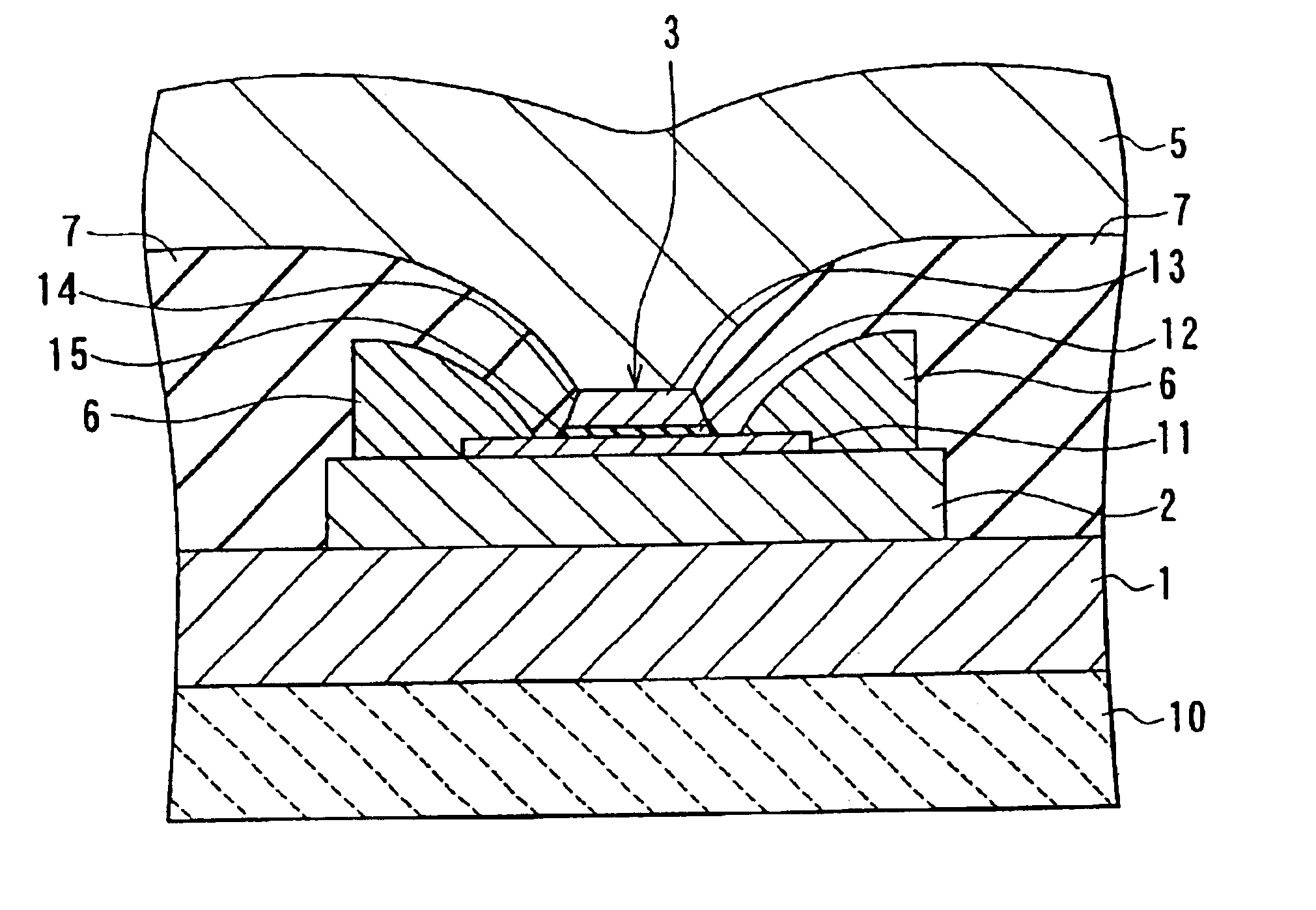
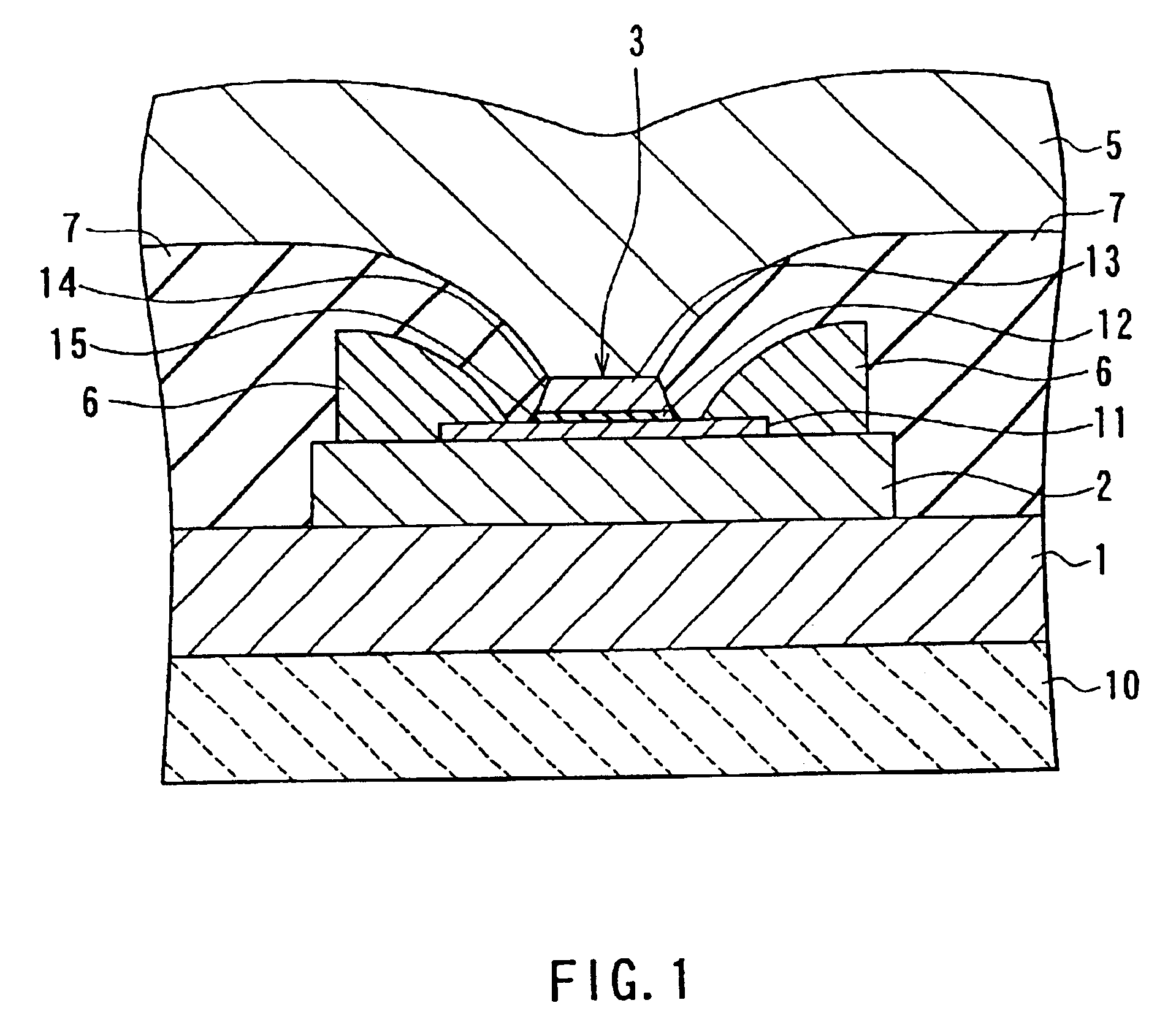
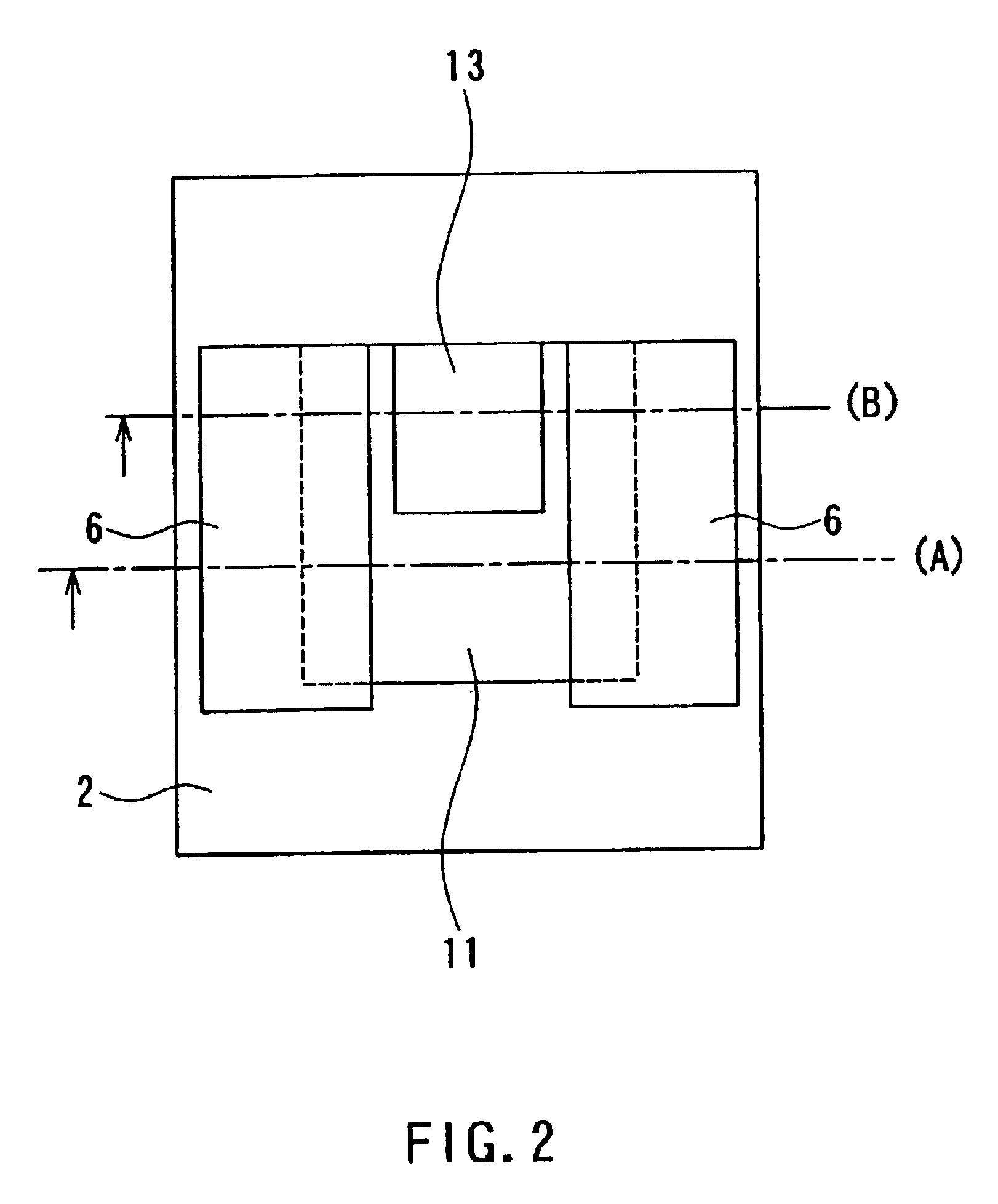
[0064]Reference is now made to FIG. 1 and FIG. 2 to describe an example in which configurations of a tunnel magnetoresistive element and a thin-film magnetic head of a first embodiment of the invention are shown. FIG. 1 is a cross section illustrating the configuration of the thin-film magnetic head of this example. FIG. 2 is a top view of the head shown in FIG. 1. FIG. 1 is the cross section parallel to a medium facing surface that faces toward a recording medium. FIG. 2 illustrates the state before the medium facing surface is formed. According to the head of this example, the structure shown in FIG. 2 is polished from the bottom part of FIG. 2 to the level indicated with alternate short and long dash line (A) or (B) to form the medium facing surface.

[0065]The thin-film magnetic head of this example functions as a reproducing (read) head that reproduces data magnetically recorded on a recording medium. The thin-film magnetic head comprises: a lower-electrode-cum-...

Example

[0117]A second embodiment of the invention will now be described. A TMR element and a thin-film magnetic head of this embodiment are similar to those of the first embodiment except that the deposition layers are replaced with deposition layers made of a material that is separated through etching and deposits on the sidewalls and undergoes nitriding. A method of manufacturing the TMR element and a method of manufacturing the thin-film magnetic head of the second embodiment include nitriding to increase the resistance value of the deposition layers, in place of the oxidation of the first embodiment.

[0118]Reference is now made to FIG. 29 to FIG. 34 to describe experiments performed to determine preferable conditions for nitriding of the second embodiment. The elements used for this experiment were similar to the ones used in the experiments of the first embodiment.

[0119]FIG. 29 shows the relationship among the joint areas, the resistance values of the TMR elements, and the maximum rate...

Example

[Third Embodiment]

[0128]A memory element and a method of manufacturing the same of a third embodiment of the invention will now be described. FIG. 35 is a cross section illustrating the configuration of the memory element of the embodiment. The memory element makes up each of memory cells of a nonvolatile magnetic random access memory (hereinafter called MRAM). The MRAM comprises a plurality of bit lines 31 and a plurality of word lines 33 arranged in a matrix. Each of the memory cells of the MRAM, that is, the memory element of this embodiment comprises the TMR element 3 located between one of the bit lines 31 and one of the word lines 33 at the intersection thereof.

[0129]The TMR element 3 of the embodiment includes the free layer 11, the tunnel barrier layer 12 and the pinned layer 13 stacked, as the element 3 of the first embodiment. In the third embodiment the TMR element 3 is placed such that the free layer 11 touches the bit line 31. An insulating layer 32 is provided between ...


PUM

PropertyMeasurementUnit
Electrical resistanceaaaaaaaaaa

Abstract

A TMR element includes: a free layer formed on a lower gap layer; a tunnel barrier layer formed on the free layer; and a pinned layer formed on the tunnel barrier layer. The pinned layer and the tunnel barrier layer have sidewalls formed through etching. The TMR element further comprises a deposition layer made of a material that is separated by etching and deposits on the sidewalls and undergoes oxidation.

Description

[0001]This is a division of application Ser. No. 09 / 749,582 filed Dec. 28, 2000, now abandoned.BACKGROUND OF THE INVENTION[0002]1. Field of the Invention[0003]The present invention relates to a tunnel magnetoresistive element utilizing the tunnel magnetoresistive effect, a thin-film magnetic head and a memory element incorporating the tunnel magnetoresistive element, and methods of manufacturing such a tunnel magnetoresistive element, thin-film magnetic head and memory element.[0004]2. Description of the Related Art[0005]Performance improvements in thin-film magnetic heads have been sought as recording density of hard disk drives has increased. Such thin-film magnetic heads include composite thin-film magnetic heads that have been widely used. A composite head is made of a layered structure including a recording head having an induction-type electromagnetic transducer for writing and a reproducing head having a magnetoresistive element for reading.[0006]Reproducing heads that exhibi...

Claims


Application Information

Patent Timeline
IPC IPC(8): G11C11/15H01F10/00G11B5/39H01F10/32G11C11/02H01F10/08H01L21/8246H01L27/105H01L43/08
CPCB82Y10/00G11B5/3903G11B5/3909G11C11/15H01F10/3254H01F10/3268B82Y25/00Y10T29/49048G11B2005/3996Y10T29/49032Y10T29/49039Y10T29/49043Y10T29/49046Y10T29/49044Y10T29/49052
Inventor SHIMAZAWA, KOJIARAKI, SATORU
Owner TDK CORPARATION
Why Eureka
Try Eureka