Differential coding of interpolation filters

a filter and interpolation technology, applied in the field of motion compensation in video coding, can solve the problems of impracticality of data rate for video recording, transmission and display applications, and inability to achieve sufficient compression. good

Active Publication Date: 2008-05-27
NOKIA TECHNOLOGLES OY
View PDF8 Cites 56 Cited by
  • Summary
  • Abstract
  • Description
  • Claims
  • Application Information

AI Technical Summary

Benefits of technology

[0042]The present invention combines the good coding efficiency of differential coding with error resilient features allowing it to be used in all environments. It is therefore particularly suited for implementation in a video coding system for use in error prone environments, for example where an encoded video bit-stream is to be transmitted over a radio communications link subject to interference.
[0052]Advantageously, the predefined base filter has a plurality of coefficient values, and a constant value is added to the coefficient values of the predefined base filter so as to reduce the amplitude of differences between the coefficient values of the interpolation filter and the coefficient values of the predefined base filter.

Problems solved by technology

Because of the relatively fast frame rate, the image content of consecutive frames tends to be quite similar, and thus consecutive frames contain a considerable amount of redundant information.
This data rate is impractical for use in video recording, transmission and display applications because of the very large storage capacity, transmission channel capacity and hardware performance required.
Sufficiently efficient compression cannot usually be achieved by simply reducing the various forms of redundancy in a given sequence of images.
Thus, most current video encoders also reduce the quality of those parts of the video sequence which are subjectively the least important.
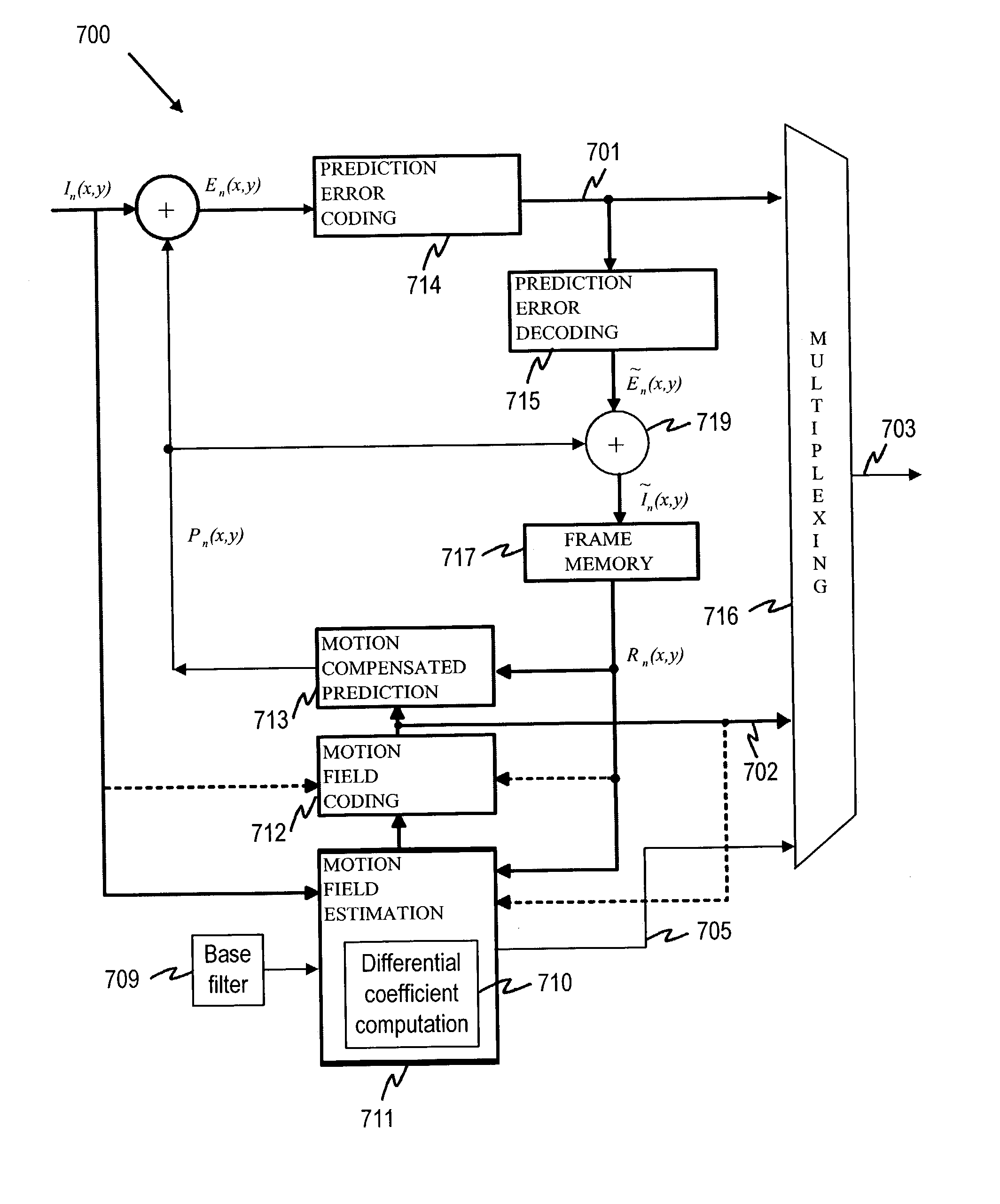
A predicted (motion-compensated, INTER-coded) image is rarely precise enough to represent the image content with sufficient quality, and therefore a spatially compressed prediction error (PE) frame is also associated with each INTER frame.
Due to the large number of pixels in a frame, it is generally not efficient to transmit separate motion information for each pixel to the decoder.
Motion estimation is a computationally intensive task.
However, this is impractical as it imposes too high a computational burden on the video encoder.
Because of the error introduced by quantization, this operation usually produces some degradation (loss of information) in the prediction error frame En(x,y).
Real motion, however, has arbitrary precision, and thus the system described above can only provide approximate modelling of the motion between successive frames of a digital video sequence.
Typically, modelling of motion between video frames with full pixel resolution is not sufficiently accurate to allow efficient minimization of the prediction error (PE) information associated with each macroblock or frame.
Thus, video coding standards, such as those previously mentioned, typically only allow motion vectors to have full-, half- or quarter-pixel resolution.
In particular, Wedi describes how aliasing in the image acquisition process, the finite resolution of allowed motion vectors and the limited validity of the translational motion model introduce additional prediction errors.
Aliasing in a video image arises due to the use of non-ideal low-pass filters (and consequent non-fulfilment of the Nyquist Sampling Theorem) in the image acquisition process.
Aliasing disturbs motion compensated prediction within the video sequence and gives rise to an additional prediction error component.
The finite precision of the allowed motion vectors (e.g., full-pixel, one-half pixel, or one-quarter pixel) and the ability of the translational motion model to represent only horizontal and vertical translational movement between successive video frames also give rise to additional prediction error contributions.
The use of dynamically adaptive interpolation filters raises an important issue relating to the coding efficiency of the encoded video data stream and also has an effect on the error resilience of the encoded video data.
As the filter coefficients are periodically updated (e.g. on a frame-by-frame basis), this necessarily adds to the amount of information to be sent from the video encoder to the decoder and has a deleterious effect on coding efficiency.
In low bit-rate video coding applications, any increase in the amount of information to be transmitted is generally undesirable.
If the information relating to the coefficient values is subject to error during its transmission from encoder to decoder, corruption of the reconstructed video data is likely.
The prior art solutions that could be used for coding interpolation filter coefficients, as mentioned above, all have problems associated with them in different usage scenarios.
The first method, in which the interpolation filter coefficients are coded separately offers inferior coding performance, since it does not utilise any a priori information (i.e., information about previously coded interpolation filter coefficient values).
Differential coding of the coefficients, as proposed in Wedi, is efficient, but may not be used in an environment with possible transmission errors, since the filter coefficients depend on correct decoding of earlier filter coefficients.
As previously described, if the encoded video bit-stream is subject to error during its transmission from encoder to decoder, corruption of the video data reconstructed at the decoder is likely to occur.
The third prior art solution with a predefined set of filters provides only limited alternatives and thus degrades the coding performance.
In other words, this option cannot achieve the full advantages of using interpolation filters with dynamically adaptive filter coefficient values, as set out in Wedi.

Method used


Image

  • Differential coding of interpolation filters
  • Differential coding of interpolation filters
  • Differential coding of interpolation filters

Examples


Embodiment Construction

[0096]The encoder, according to the present invention, codes filter coefficients differentially with respect to predefined base filter coefficients. FIGS. 6a-6c illustrate the method according to the present invention. The bar graphs presented in FIG. 6a are representative of interpolation filter coefficient values, each bar corresponding to one of the filter coefficients. The height of a bar represents the respective coefficient value, bars extending above the horizontal axis representing positive coefficient values, bars extending below the horizontal axis, negative coefficient values. Referring to FIG. 6a and FIG. 6b, the bar graph 110 represents the filter that the encoder detects to be best suited for motion interpolation of a selected image segment, while the bar graph 140 represents the base filter. In the example shown in FIG. 6a, the filter is a 6-tap symmetric filter having 6 filter coefficients. Instead of sending the filter coefficients as such, only the differences 130 ...


PUM


Abstract

A video coding system for coding a sequence of video frames each having an array of pixel values is provided. The system includes an interpolation filter to reconstruct sub-pixel values for use in the inter-frame prediction process. The coefficients of an interpolation filter are obtained differentially with respect to a predefined base filter in order to provide a set of difference values. As the base filter coefficients are known to both encoder and decoder and they are statistically close to the actual filters used in the video sequence, the decoder can reconstruct the pixel values based on the set of difference values.

Description

[0001]This application is based on and claims the benefit of U.S. Provisional Patent Application No. 60 / 348,811, filed Jan. 14, 2002.FIELD OF THE INVENTION[0002]The present invention relates to motion compensation in video coding. More specifically, the invention concerns a method for coding the coefficients of interpolation filters used to reconstruct image pixel values in motion compensated video encoders and decoders. The invention also relates to a corresponding video encoder, video decoder and video transmission system that implement the method of the invention.BACKGROUND OF THE INVENTION[0003]Today there are various video coding standards in existence. These include International Telecommunications Union Telecommunications Standardization Sector (ITU-T) recommendation H.263, and International Standards Organization (ISO) Motion Pictures Expert Group (MPEG) standards MPEG-1, MPEG-2 and MPEG-4. These video coding standards are based on the use of motion compensated prediction an...

Claims


Application Information

Patent Timeline
Patent Type & Authority Patents(United States)
IPC IPC(8): H04N7/12G06K9/36G06T9/00H03M7/36H04N19/50H04N19/80H04N19/89
CPCH04N19/197H04N19/176H04N19/172H04N19/46H04N19/196H04N19/523H04N19/117H04N19/463H04N19/136H04N19/80H04N19/89H04N19/61H04N19/50
Inventor LAINEMA, JANI
Owner NOKIA TECHNOLOGLES OY
Why Eureka
Try Eureka