Material dewatering apparatus

a technology of dewatering apparatus and material, which is applied in the direction of water/sludge/sewage treatment, using liquid separation agent, dispersed particle filtration, etc., can solve the problems of unsuitability unless, need to use a dryer, etc., and achieve the effect of considerable efficiencies

Inactive Publication Date: 2008-06-03
SOLID SOLUTIONS
View PDF10 Cites 20 Cited by
  • Summary
  • Abstract
  • Description
  • Claims
  • Application Information

AI Technical Summary

Benefits of technology

[0005]According to the invention, there is provided a pneumatic de-watering apparatus for wet product comprising a cyclone chamber connected to a fan with blades, each blade causing individual flow vortices to be formed downstream of the fan which in turn combine to form cyclonic flow within the cyclone chamber characterized in that the cyclone chamber comprises at least a vortex flow forming section having vortex flow forming means to cause reformation of vortex flow within the cyclone chamber on dissipation of the vortex flow along the cyclone chamber remote from the fan. While if is known to produce such cyclone chambers, heretofore there has been no attempt to reform the vortex or, more importantly, to concentrate the vortex within the cyclone chamber. It will be appreciated that as the air is drawn through the cyclone chamber, the cyclone dissipates towards its proximal end. By re-concentrating and reforming the vortex flow, considerable efficiencies area achieved.
[0006]In one embodiment of the invention, the cyclone chamber comprises a vortex flow shedding section fed by the vortex flow forming section. This construction is unique because now within the cyclone chamber, there is a controlled vortex flow shedding immediately following vortex formation and in this way, the material can be treated under controlled conditions.
[0007]In one embodiment of the invention, the vortex flow shedding section is downstream of the fan, the vortex flow shedding section being arranged and configured such that the individual vortex flows developed by each fan blade are substantially destroyed within the vortex flow shedding section. It is believed that these individual vortices, that is to say, the individual vortex flows, when they are allowed progress, as it were, through the whole of the cyclone chamber, they effectively form a long winding high friction vortex it has been envisaged that if those individual vortices can be shed adjacent the fan, this greatly facilitates the virtually friction-free centripetal vortex flow formation of a single vortex flow ability to generate various forms along the cyclone chamber which acts much better than would be expected to dewater the material. It is, however, envisaged that this may not all be destroyed in a first vortex flow shedding chamber but may in fact require further vortex flow shedding chambers along the cyclone chamber to achieve the necessary result.
[0011]Ideally, the vortex flow is a centripetal vortex flow. This is the preferred type of vortex flow and has considerable advantages in treating, for example, wet sewage.

Problems solved by technology

The problem is that the rest of the material collects along the walls of the apparatus on the impeller blades and indeed throughout the whole equipment Thus, for dewatering of sewage, it is unsuitable unless the sewage is pretreated.
There is thus unfortunately a need to use a dryer to treat raw sewage.

Method used


Image

  • Material dewatering apparatus
  • Material dewatering apparatus
  • Material dewatering apparatus

Examples


Embodiment Construction

[0041]The invention will be more clearly understood from the following description of some embodiments thereof, given by way of example only, with reference to the accompanying drawings, in which:

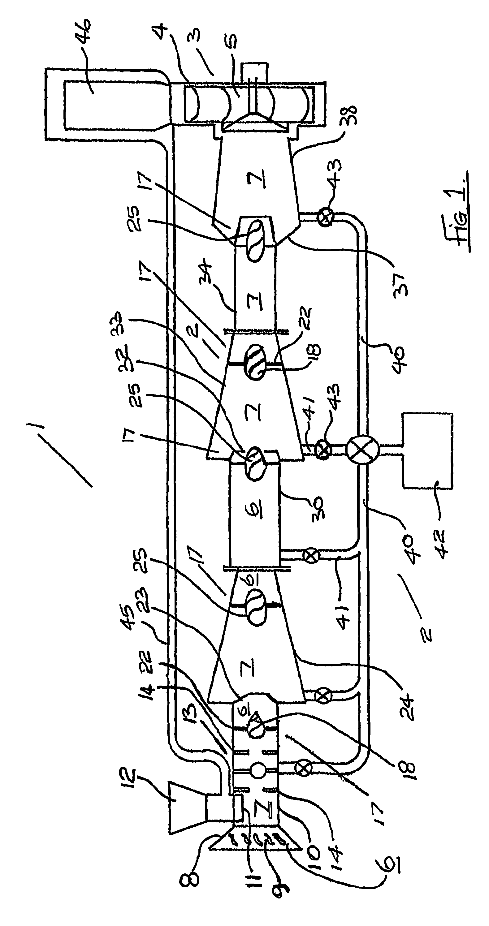
[0042]FIG. 1 is a diagrammatic sectional view of portion of an apparatus according to the invention,

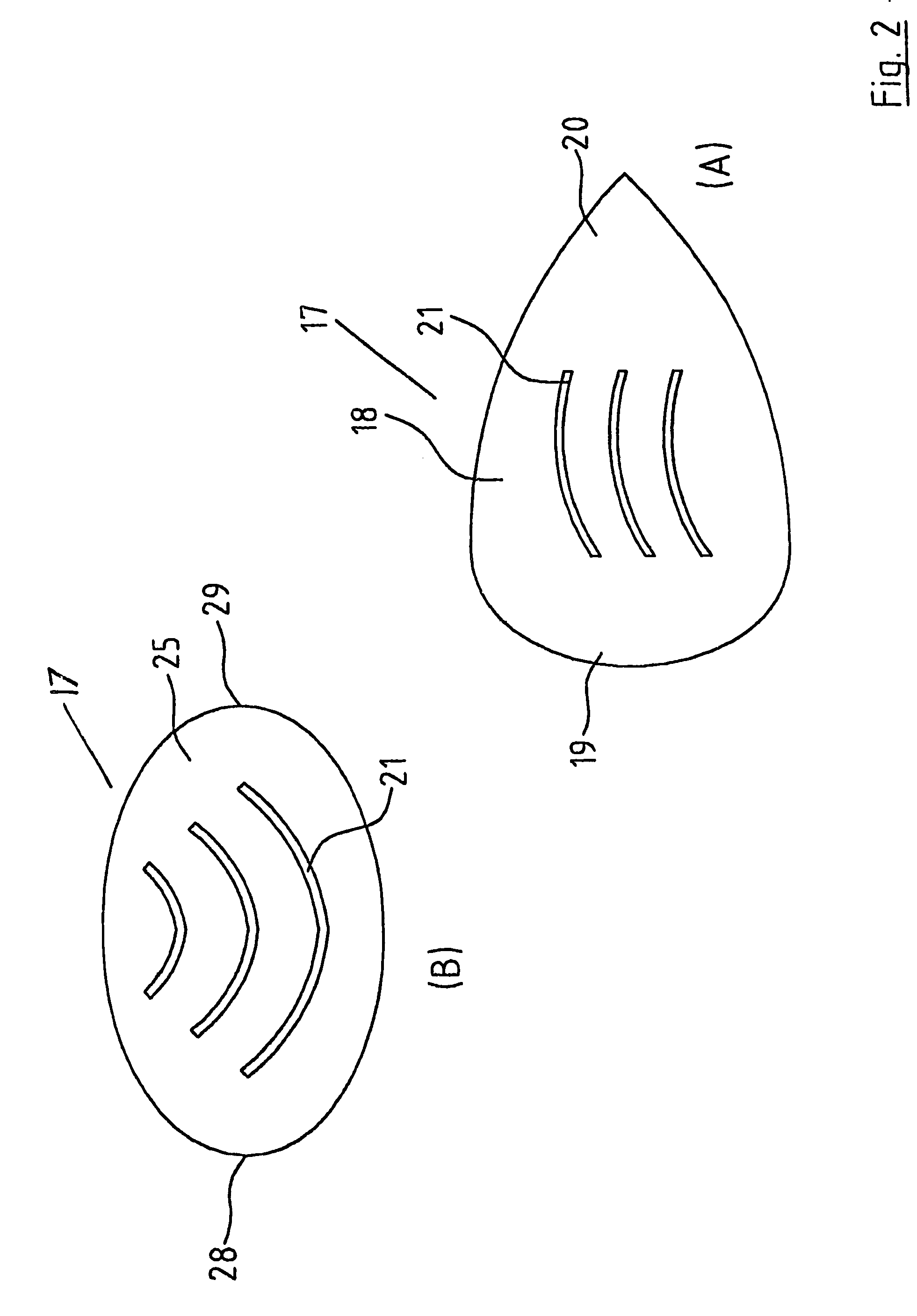
[0043]FIGS. 2(a) and 2(b) are details of portion of the apparatus of FIG. 1,

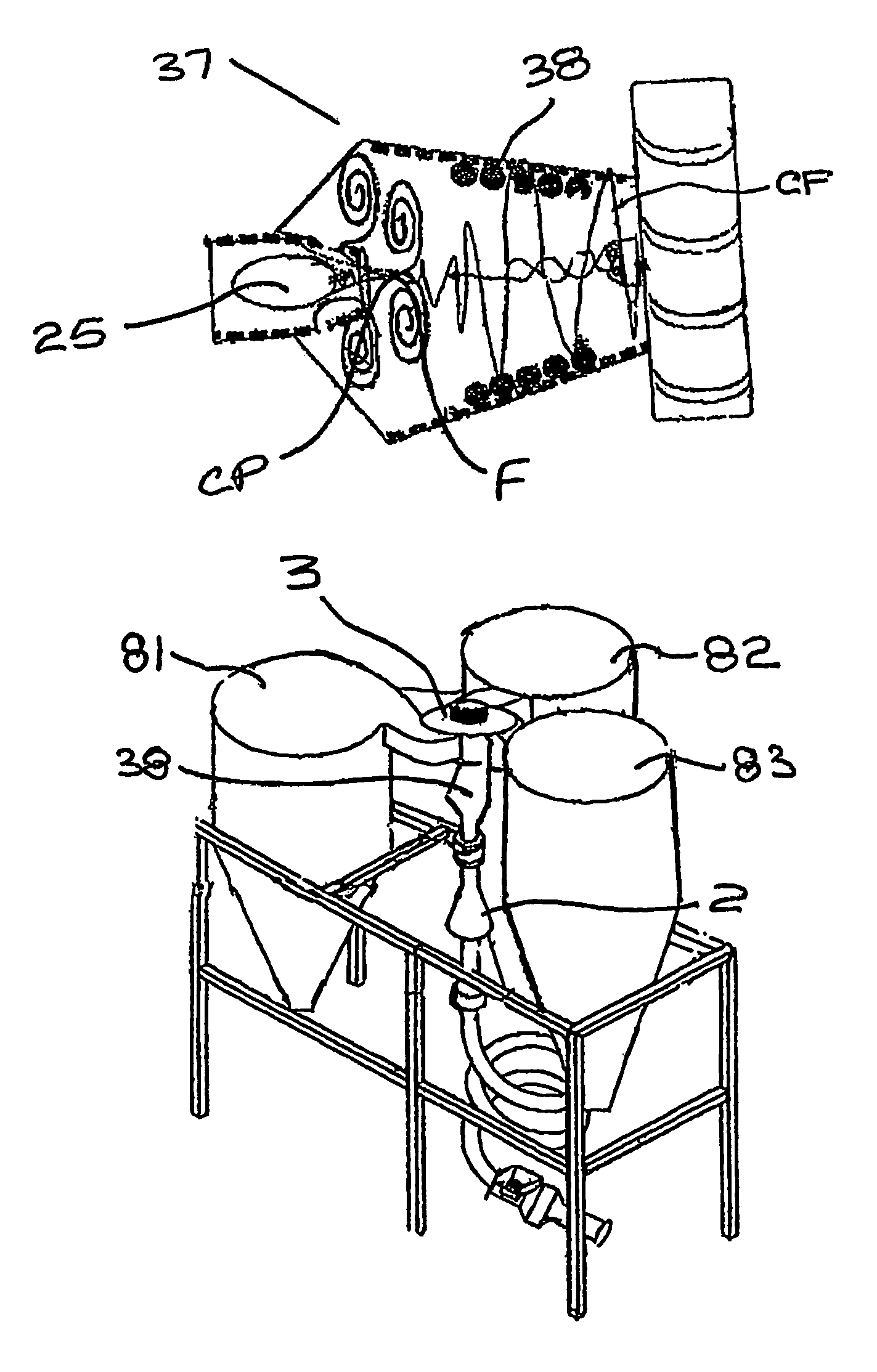
[0044]FIG. 3 is a detail of FIG. 1 showing formation of a vortex in part of the apparatus,

[0045]FIG. 4 is a further detail of FIG. 1 showing other vortices formed,

[0046]FIG. 5 illustrates a modification of the apparatus of FIGS. 1 and 2,

[0047]FIG. 6 is a diagrammatic view of an alternative construction of apparatus according to the invention,

[0048]FIG. 7 is a sectional view along the lines VII—VII of FIG. 6,

[0049]FIG. 8 is a sectional view of portion of the apparatus along the sectional lines VIII—VIII of FIG. 6,

[0050]FIG. 9 is an enlarged vertical sectional view of portion of the apparatus illustrated in FIG. 6,

[0051...


PUM

PropertyMeasurementUnit
timeaaaaaaaaaa
temperatureaaaaaaaaaa
areaaaaaaaaaaa

Abstract

The invention provides a pneumatic dewatering apparatus (1) for wet product. The apparatus (1) comprises essentially a cyclone chamber (2) connected to a centrifugal fan (3). Various vortex flow forming stations (6), each followed by a vortex shedding station (7), are mounted within the cyclone chamber (2). Tight centripetal vortices are formed and are then shed such that water is delivered out the cyclone chamber (2) into a sump (42).

Description

[0001]This is a nationalization of PCT / IE03 / 00062 filed Apr. 29, 2003 and published in English.[0002]The present invention relates to a pneumatic dewatering apparatus for wet product comprising a cyclone chamber connected to a fan with blades, each blade causing individual flow vortices to be formed downstream of the fan which in turn combine to form cyclonic flow within the cyclone chamber. It further relates to a pneumatic method of dewatering wet product.[0003]Such apparatus is already well known, such as, for example, the apparatus for granulating, drying or de-watering a material as disclosed. In PCT Published Specification No. WO 98 / 35756 (Next Century Technologies Limited), one of the inventors of which is the inventor of the present application. The apparatus comprises an impeller suction fan and a cyclone chamber that can be varied in length to produce a range of, harmonics.[0004]Drying is effected through a known dewatering apparatus or this type, we believe, ionization, t...

Claims


Application Information

Patent Timeline
Patent Type & Authority Patents(United States)
IPC IPC(8): F26B5/08B01D45/00C02F1/34B04C3/00B04C3/04B04C5/14B04C5/26B04C9/00C02F11/00C02F11/12F26B17/10
CPCB04C3/00B04C3/04B04C9/00F26B17/104F26B17/105F26B17/107B04C2009/005F26B2200/18
Inventor SEEBACH, CHRISTOPHER FREDERICK NEILAN
Owner SOLID SOLUTIONS
Why Eureka
Try Eureka