Solar energy concentrator for power plants

a technology of solar energy and power plants, applied in the field of concentrators, can solve the problems of inherently expensive and inefficient mirrors mounted on pedestals, proved to be much too expensive and inefficient for widespread commercial use, and the effect of high cost and poor performance of plants

Active Publication Date: 2008-06-03
RATLIFF GEORGE D
View PDF2 Cites 55 Cited by
  • Summary
  • Abstract
  • Description
  • Claims
  • Application Information

AI Technical Summary

Problems solved by technology

They proved to be much too expensive and inefficient for widespread commercial use.
The high cost and poor performance of the plants was attributed to the heliostats used as solar concentrators.
Mirrors mounted on pedestals are inherently expensive and inefficient.
When these earlier plants were built there were no suitable mobile-mirror solar concentrators.
One disadvantage is the cost of the large number of pistons, hoses, cable reels, and rack and pinion drives required.
Another disadvantage is the amount of land and track required.
Still another disadvantage is the weight and complexity of roof panels attached to the mirrors.

Method used


Image

  • Solar energy concentrator for power plants
  • Solar energy concentrator for power plants
  • Solar energy concentrator for power plants

Examples


Embodiment Construction

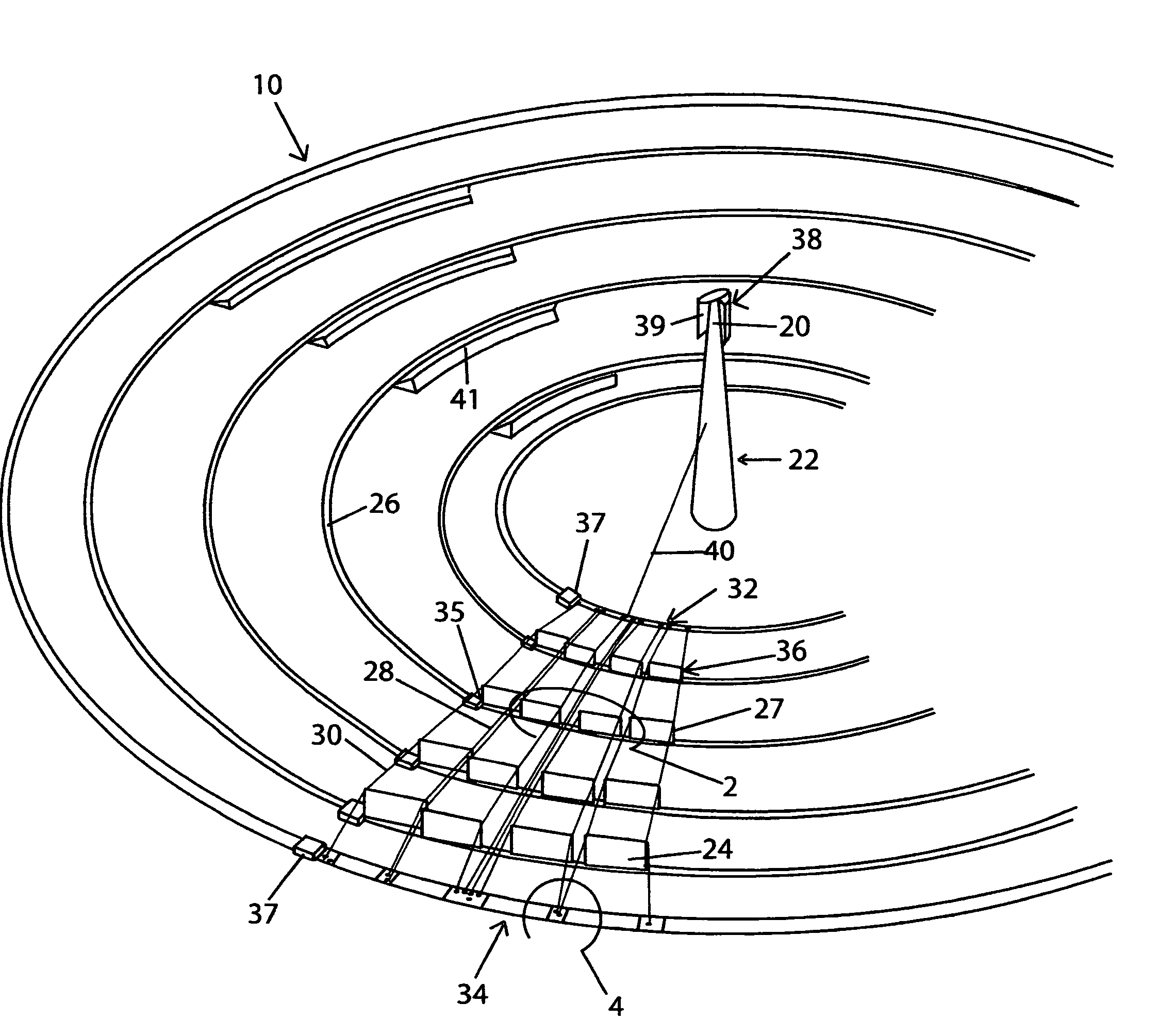
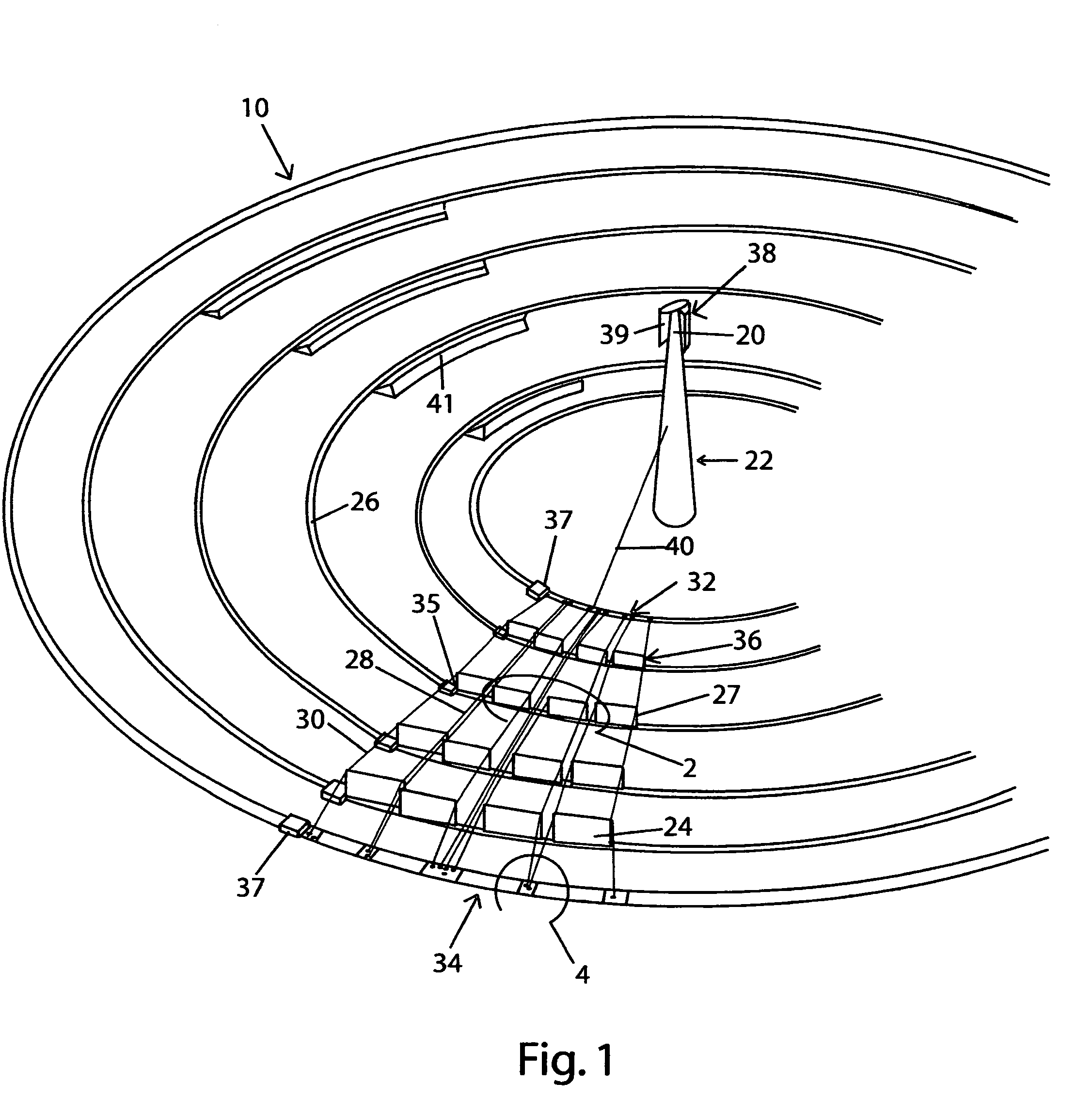
[0016]FIG. 1 is an overall view of the solar concentrator 10. The concentrator includes a central receiver 20 on a tower 22 and mirrors 24 (shown from behind) that move around the tower 22 on concentric circular tracks 26. The mirrors are braced by radially extending cables 28, 30. The cables are anchored to an innermost anchorage train 32 and an outermost anchorage train 34. Mirror locomotives 35 pull the mirror-frame trains 36 and anchorage locomotives 37 pull the anchorage trains 32, 34 around the tower synchronized with azimuthal change of the sun's position. The receiver 20 has a rotating hood 38 with secondary mirrors 39 on the inside of the hood 38. An umbilical connection 40 delivers electricity and computer commands from the tower 22 to operate motors on the trains. Low walls 41 beside the tracks extend the full length of the mirror-frame trains 36 on their respective tracks 26.

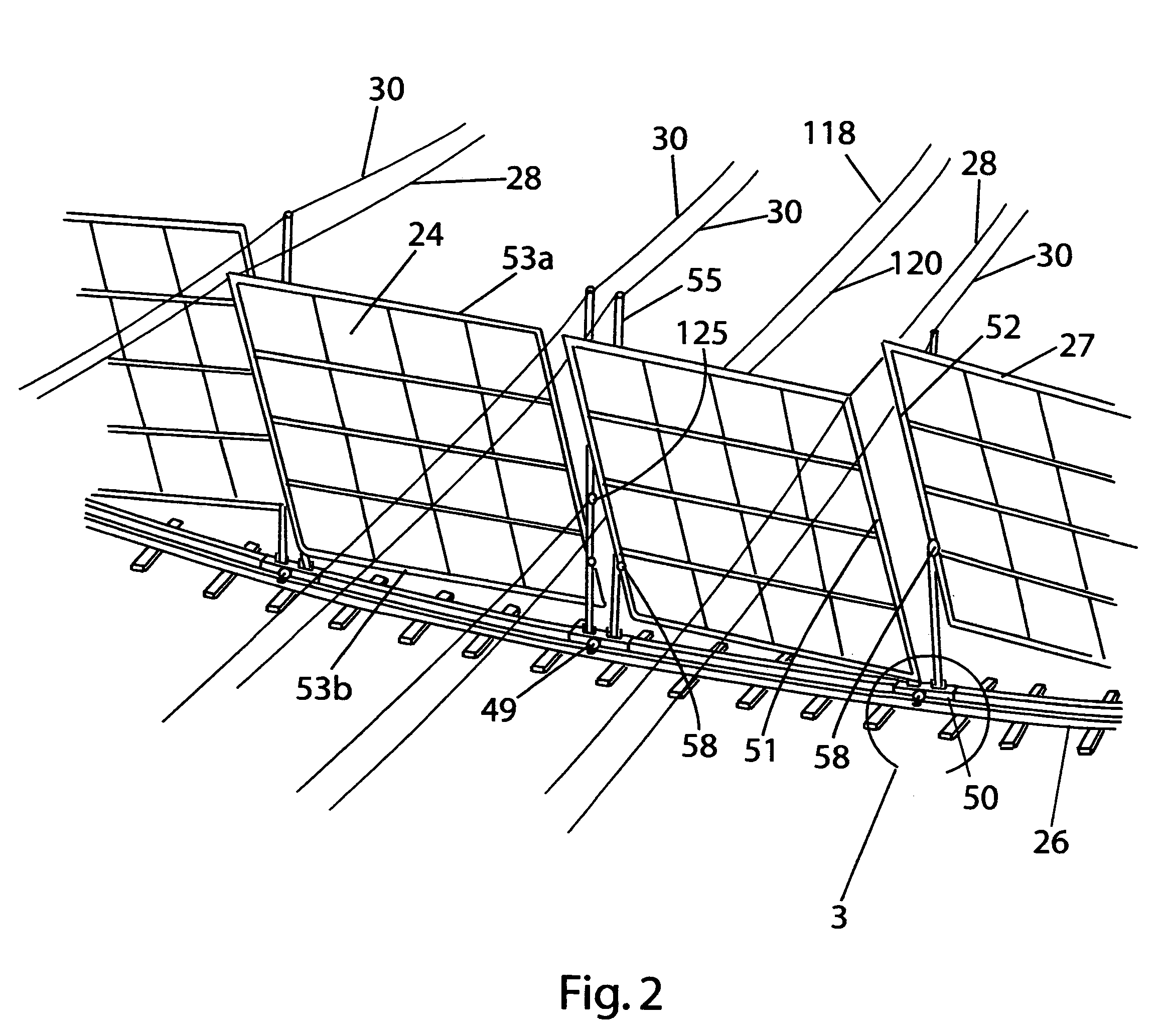
[0017]FIG. 2 is an enlarged close-up view of a portion of a mirror-frame train 36 shown in FIG. 1...


PUM


Abstract

A solar concentrator includes a mirror 24 having a frame 27 connected with a lever 55, a train 36 supporting the frame 27 and the lever 55, a first control cable 28 connected with the frame 27, and a second control cable 30 connected with the lever 55. A first locomotive 35 moves the train along a curvilinear path to keep the mirror 24 opposite the sun. The first control cable 28 controls pitch of the mirror 24 and the second control cable 30 controls yaw of the mirror 24. When a concentrator includes a plurality of mirrors 24 they are preferably controlled collectively by pulling all of the first control cables 28 with one motor to control pitch and by pulling all of the second control cables 30 with one motor to control yaw. Sunlight focused on the receiver 20 preferably boils water to form steam that is transmitted to a turbine connected to a generator for producing electricity.

Description

BACKGROUND[0001]1. Field of the Invention[0002]This invention relates to a concentrator for focusing sunlight onto a central receiver by means of mirrors revolving around the receiver. Central-receiver concentrators can be used to produce the high-pressure steam needed in power plants.[0003]2. Discussion of the Prior Art[0004]Sunlight can replace coal, natural gas, or uranium as the source of energy for electric power plants. Sunlight must be collected and concentrated to obtain the high temperature needed for producing high-pressure steam used in power plants. Several high-pressure steam solar power plants were built in the 1970's and early 1980's. They proved to be much too expensive and inefficient for widespread commercial use.[0005]The high cost and poor performance of the plants was attributed to the heliostats used as solar concentrators. Heliostats include massive steel and concrete pedestals supporting mirrors that rotate about 2 axes to keep sunlight focused on a central r...

Claims


Application Information

Patent Timeline
Patent Type & Authority Patents(United States)
IPC IPC(8): F24J2/38F24S50/20
CPCF24J2/07F24J2/5406F24J2002/5458F24J2002/5479Y02B10/20Y02E10/41Y02E10/47F24S20/20F24S30/422F24S2030/133F24S2030/145Y02E10/40
Inventor RATLIFF, GEORGE D.
Owner RATLIFF GEORGE D
Why Eureka
Try Eureka