Mounting arrangement for coverings for architectural openings

a technology for mounting arrangements and openings, applied in the direction of curtain suspension devices, shutters/movable grilles, door/window protective devices, etc., can solve the problems of cords dragging on the floor and hard to reach

Active Publication Date: 2008-06-03
HUNTER DOUGLAS INC
View PDF46 Cites 72 Cited by
  • Summary
  • Abstract
  • Description
  • Claims
  • Application Information

AI Technical Summary

Benefits of technology

[0009]The present invention provides a cord drive which has the advantages of prior art cord drives, plus it eliminates the problems with prior art cord drives which may be too high to reach or which may drag the floor. One embodiment of the present invention provides a single cord drive which does not require the drive cord to travel as far as the window covering. It also permits the use of this single cord drive in unpowered, underpowered, or overpowered blinds and shades.
[0011]Also, in some of the embodiments, the distance traversed by the drive cord to fully raise or lower the shade is a fraction of the distance traversed by the shade itself. In some embodiments, the distance traversed by the drive cord is 65% or less of the distance traversed by the shade, while the force required at any point to raise or lower the shade is less than 1.5 times the weight of the shade being raised or lowered. Furthermore, even for large shades, the force required at any point to raise or lower the shade generally is less than 15 pounds, making the shade easy for anyone to use.

Problems solved by technology

The cords in a cord drive, for instance, may be such that they are either hard to reach when the cord is way up (and the blind is in the fully lowered position), or the cord may drag on the floor when the blind is in the fully raised position.

Method used


Image

  • Mounting arrangement for coverings for architectural openings
  • Mounting arrangement for coverings for architectural openings
  • Mounting arrangement for coverings for architectural openings

Examples


first embodiment

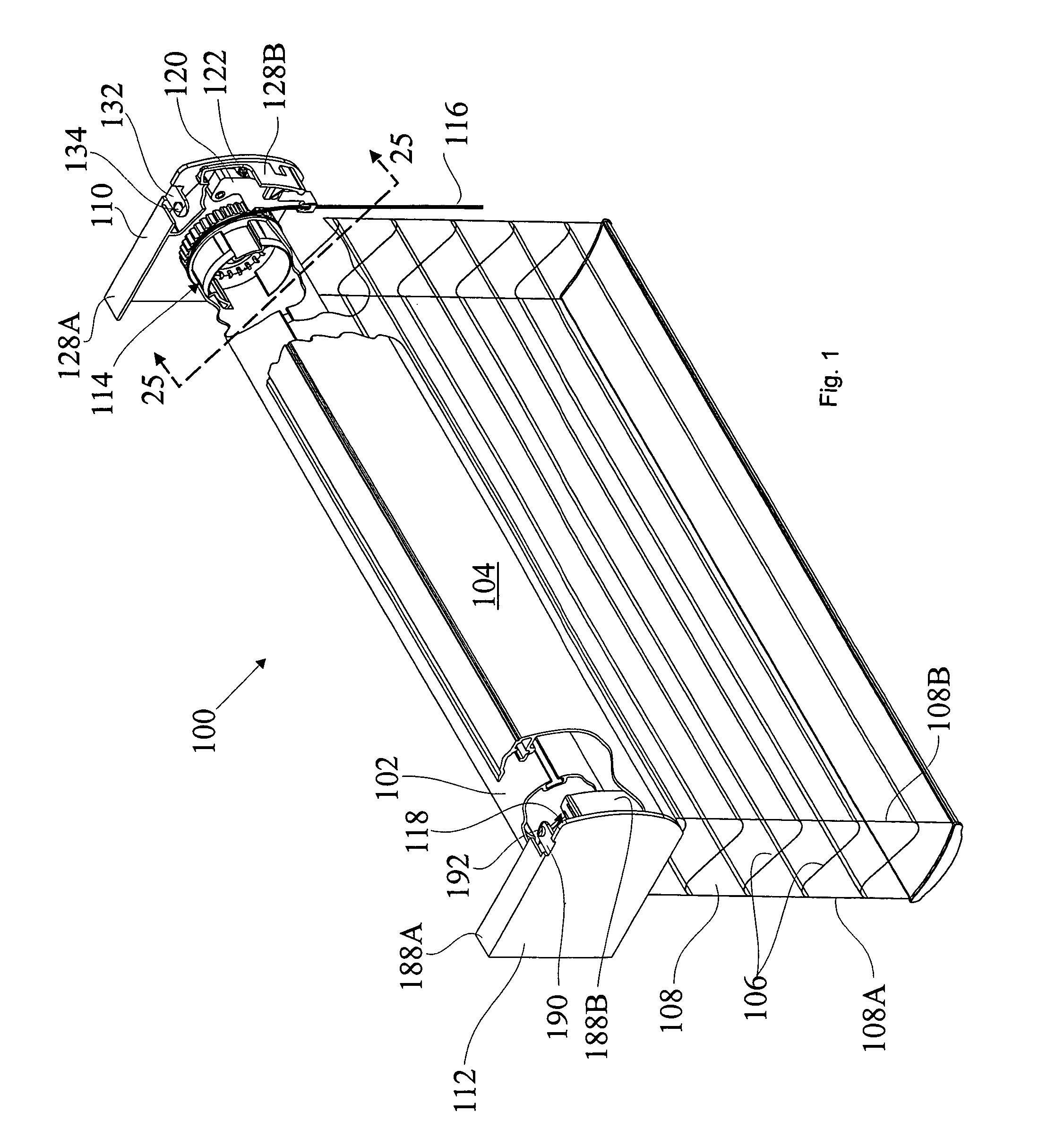
[0111]FIGS. 1 through 6 illustrate various embodiments of the present invention as it relates to horizontal variable light control shades. FIG. 1 is a partially broken away, perspective view of a shade 100 utilizing a spring assist automatic brake 114 (illustrated in further detail in FIGS. 24 through 28) to hold the shade in the desired position once the drive cord is released, and a clock spring assembly 118 (illustrated in further detail in FIGS. 7 and 8) to assist in tilting the shade fully open when the shade is in the fully lowered position.

[0112]The shade 100 of FIG. 1 includes a rotator rail 102, a head rail cover 104, and a plurality of slats 106 suspended from the rotator rail 102 by means of ladder tapes 108 (108A and 108B). In this embodiment, the ladder tapes 108 extend for the full width of the blind. End caps 110 and 112 are used to mount the shade 100 to the architectural opening.

[0113]At the right end (also referred to as the control end) of the blind 100, a spring ...

second embodiment

[0185]FIG. 50 depicts a spring clamp brake 500 made in accordance with the present invention. This brake 500 is identical in its operation and of very similar manufacture to the clamp spring brake 272 of FIG. 11, the main difference being in the spool-to-rail adapter 502.

[0186]As seen in FIG. 51, the spool-to-rail adapter 502 (also called the drive cord spool 502) is similar to the adapter 286 of FIG. 11. It includes an annular disk 546, which defines a groove 548 along its perimeter, where the drive cord 116 winds up onto the drive cord spool 502. A single opening 550 extends from the inner surface 547 of the disk 546 to the groove 548, so the drive cord 116 may be threaded through the opening 550 and tied off with a knot or grommet (not shown).

[0187]A hollow cylindrical projection 552 projects inwardly from the inner surface 547 of the disk 546. The outside surface 558 of the cylindrical projection 552 includes a plurality of radially extending wings 560 sized to slide into and en...

third embodiment

[0189]FIG. 53 depicts a spring clamp brake 600 made in accordance with the present invention. This brake 600 is identical in its operation and of very similar manufacture to the spring clamp brake 272 of FIG. 11, the main difference being in the two-piece, spool-to-rail adapter 602, 604.

[0190]As seen in FIG. 54, the spool-to-rail adapter 602, 604 (also called the drive cord spool) is a two piece design which is similar to the single piece design 286 of FIG. 11. It includes an annular disk 646, which defines a groove 648 along its perimeter, where the drive cord 116 winds up onto the drive cord spool 602. A single opening 650 extends from the inner surface 647 of the disk 646 to the groove 648, so the drive cord 116 may be threaded through the opening 650 and tied off with a knot or grommet (not shown).

[0191]A hollow cylindrical projection 652 projects inwardly from the inner surface 647 of the disk 646. The outside surface 658 of the cylindrical projection 652 includes a plurality o...


PUM


Abstract

A shade for architectural openings incorporating a single cord drive featuring automatic braking of the shade when the user releases the drive cord. In a preferred embodiment, an automatic tilt-open mechanism is provided to tilt the shade open when the shade is in the fully extended down position.

Description

[0001]This application claims priority from U.S. Provisional Application Ser. No. 60 / 461,549, filed Apr. 9, 2003, which is hereby incorporated by reference. The present invention relates to a cord drive for producing rotary motion. In the embodiments shown here, the cord drive is used for raising and lowering coverings for architectural openings such as Venetian blinds, pleated shades, and other blinds and shades. This cord drive may also be used on vertical blinds and other mechanical devices requiring rotary motion.BACKGROUND OF THE INVENTION[0002]Typically, a blind transport system will have a top head rail which both supports the blind and hides the mechanisms used to raise and lower or open and close the blind. Such a blind system is described in U.S. Pat. No. 6,536,503, Modular Transport System for Coverings for Architectural Openings, which is hereby incorporated by reference. In the typical top / down product, the raising and lowering of the blind is done by a lift cord suspen...

Claims


Application Information

Patent Timeline
Patent Type & Authority Patents(United States)
IPC IPC(8): E06B9/17
CPCE06B9/34E06B9/50E06B9/40E06B2009/2435Y10S160/903
Inventor ANDERSON, RICHARD N.HAARER, STEVEN R.FRASER, DONALD E.FISHER, II, ROBERT E.
Owner HUNTER DOUGLAS INC
Why Eureka
Try Eureka