Quick disconnect assembly having a finger lock assembly

a technology of finger lock and assembly, which is applied in the field of quick disconnect assembly to achieve the effect of reducing the envelop

Inactive Publication Date: 2008-06-03
VARIAN MEDICAL SYSTEMS
View PDF27 Cites 13 Cited by
  • Summary
  • Abstract
  • Description
  • Claims
  • Application Information

AI Technical Summary

Benefits of technology

[0015]In another broad aspect, instead of only providing for single use, multiple use of a detachable assembly is provided by eliminating the breakaway collar and utilizing spring biasing means.
[0016]The present invention provides a unique capability of providing two simultaneous countercurrent flow paths. This benefit is particularly applicable for certain cryosurgical probe system applications in which there are simultaneous input and output flows. Furthermore, the finger lock element provides a minimized envelope.

Problems solved by technology

There is an inherent problem with this type of system inasmuch as each cryosurgical probe assembly is typically used only once due to sterilization and performance factors.

Method used


Image

  • Quick disconnect assembly having a finger lock assembly
  • Quick disconnect assembly having a finger lock assembly
  • Quick disconnect assembly having a finger lock assembly

Examples


Embodiment Construction

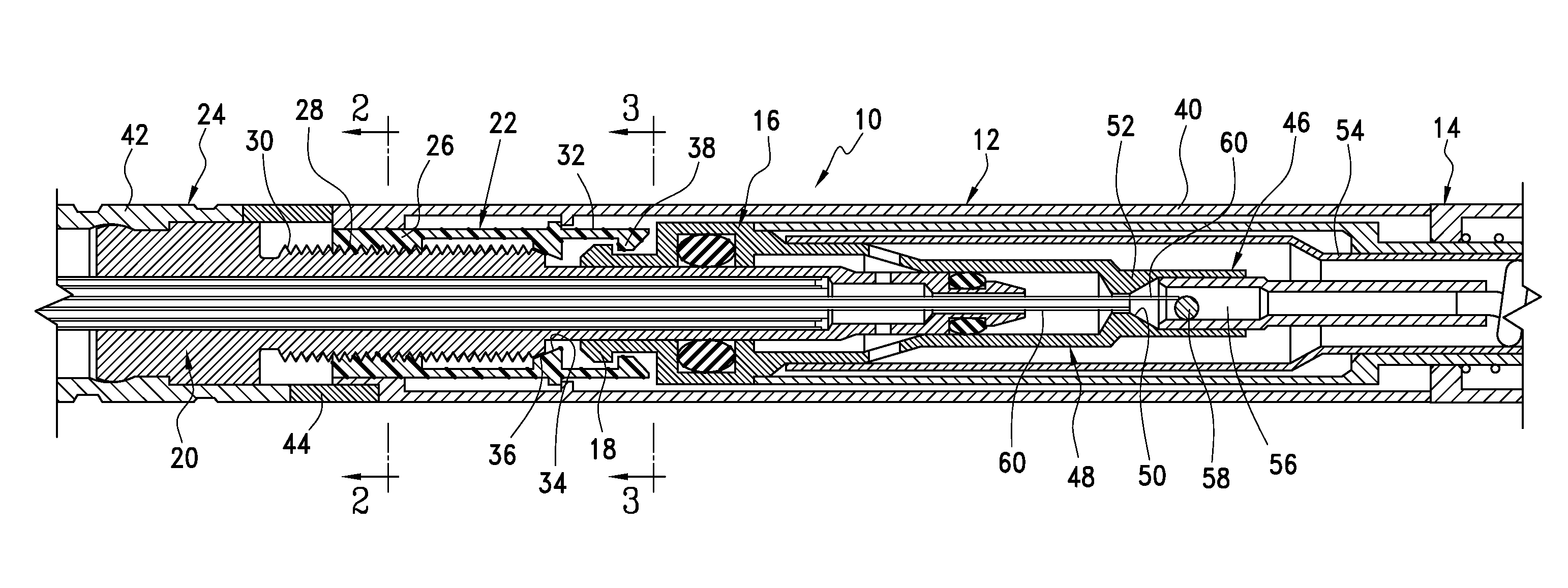
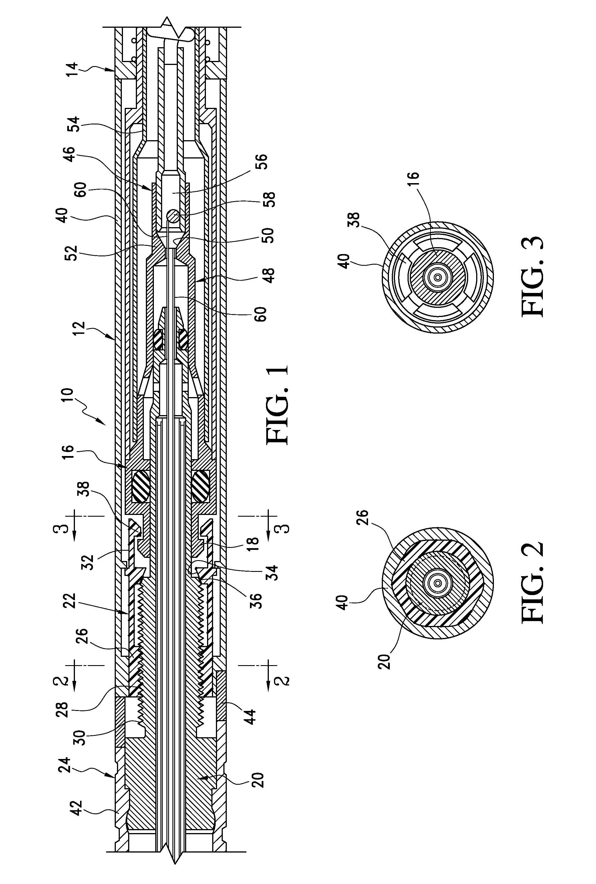
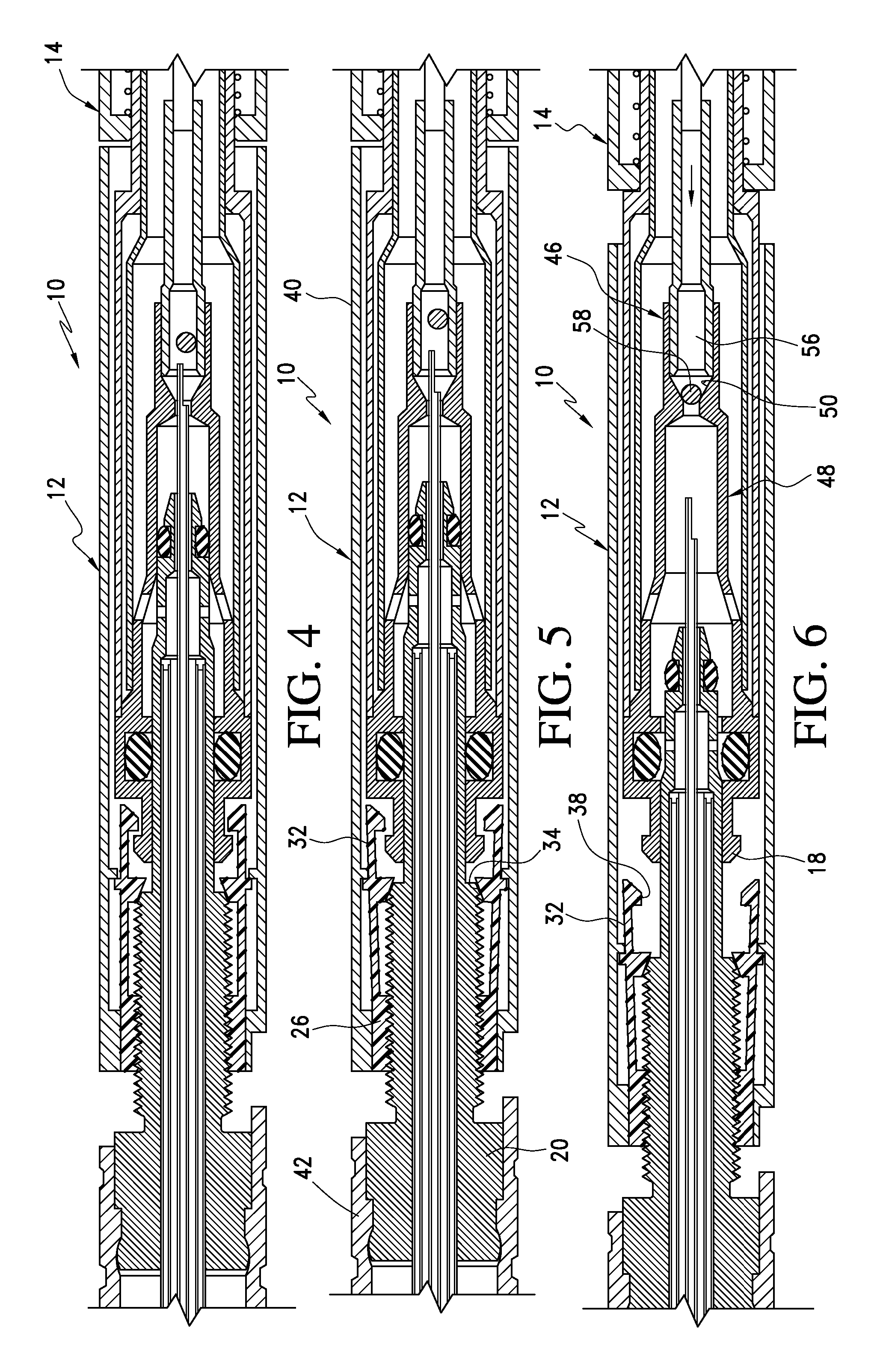
[0036]Referring now to the drawings and the characters of reference marked thereon, FIG. 1 illustrates a first embodiment of the quick disconnect assembly of the present invention, designated generally as 10. In this first embodiment the quick disconnect assembly includes a single use, disposable assembly 12 and a reusable assembly, designated generally as 14. In the parent application to this patent application the disposable assembly 12 and the reusable assembly 14 are explained in detail as applied in a cryosurgical probe system. The parent application, U.S. Ser. No. 11 / 116,873, entitled Detachable Cryosurgical Probe With Breakaway Handle, filed Apr. 28, 2005, is incorporated by reference herein, in its entirety. FIG. 1 of the present patent application shows the attaching portions of the disposable assembly 12 and the reusable assembly 14, as applied to this cryosurgical probe system. However, this disconnect assembly 10 can be used in numerous applications involving fluid trans...


PUM


Abstract

The quick disconnect assembly includes a reusable assembly including a distal end having a male lip thereon; and, a disposable assembly having quick disconnect capabilities when utilized with the reusable assembly. The disposable assembly includes a stem section; a finger lock element; and, a detachable handle assembly. The finger lock element includes a distal finger lock element section having a threaded inner surface for engagement with a threaded outer surface of the stem section; and, a plurality of radially spaced fingers extending proximally from the distal finger lock element section. Each finger has a) a ramped surface for operatively engaging an associated ramp section on the stem section during use; and, b) a female lip at a proximal end thereof. The detachable handle assembly includes a proximal handle section having a distal end having an inner surface that is operatively engaged with an outer surface of the finger lock element so as to resist relative rotation and axial motion therebetween. A distal handle section of the detachable handle assembly includes a distal handle section having an inner surface that is operatively engaged with another outer surface of the stem section so as to resist relative rotation and axial motion therebetween. A breakaway collar of the detachable handle assembly is positioned between the proximal handle section and the distal handle section. When the disposable assembly is attached, the breakaway collar is an integral unit which prevents relative rotation between the proximal handle section and the distal handle section, the female lip engaging the male lip at a distal end of the reusable assembly, thereby securing the reusable assembly to the disposable assembly. The quick disconnect assembly may be used to provide only a mechanical connection or it may be provided with components for providing fluid transfer. In another embodiment, instead of only providing for single use, multiple use of a detachable assembly is provided by eliminating the breakaway collar and utilizing spring biasing means.

Description

CROSS REFERENCE TO RELATED APPLICATIONS[0001]This is a continuation-in-part of U.S. Ser. No. 11 / 116,873, entitled Detachable Cryosurgical Probe With Breakaway Handle, filed Apr. 28, 2005, which is a continuation-in-part of U.S. Ser. No. 10 / 603,883, entitled Detachable Cryosurgical Probe, filed Jun. 25, 2003.BACKGROUND OF THE INVENTION[0002]1. Field of the Invention[0003]The present invention relates to quick disconnect assemblies and more particularly to a quick disconnect assembly that utilizes a finger lock assembly for providing effective disconnect capabilities for both single and multiple uses; and, for with both purely mechanical systems and for systems that provide for fluid transfer.[0004]2. Description of the Related Art[0005]Cryosurgery involving the use of a cryosurgical probe assemblies typically involves the use of cryoprobes that are each attached to a handle that are, in turn, connected to a high-pressure fluid line with a quick-disconnect for attachment to a fluid so...

Claims


Application Information

Patent Timeline
Patent Type & Authority Patents(United States)
IPC IPC(8): A61B18/02
CPCA61B18/02A61B2017/00274A61B2019/5425A61B2018/00547A61B2018/0262A61B2017/0046A61B2090/3925
Inventor DUONG, THACHEUM, JAY J.
Owner VARIAN MEDICAL SYSTEMS
Why Eureka
Try Eureka