Liquid crystal display unit having back-light with fluorescent tubes and fresnel lens with longitudinal cuts perpendicular to tubes

a liquid crystal display and fluorescent tube technology, applied in the field of liquid crystal display units, can solve the problems of poor display quality of the display unit, difficulty in perfect parallel output of backlight, and high cost, and achieve the effect of improving the display quality and preventing the appearance of whitish liquid crystal display panels

Inactive Publication Date: 2008-06-03
SHARP KK
View PDF15 Cites 0 Cited by
  • Summary
  • Abstract
  • Description
  • Claims
  • Application Information

AI Technical Summary

Benefits of technology

[0010]In order to solve the problems described above, preferred embodiments of the present invention provide a liquid crystal display unit that uses a back-light that does not output perfectly parallel light and that can prevent a whitish appearance of a liquid crystal display panel so as to improve its display quality and to provide a display unit including the liquid crystal display unit.
[0011]The liquid crystal display unit according to a preferred embodiment of the present invention includes a liquid crystal display panel, a back-light arranged to output light to the liquid crystal display panel, and a scattering-anisotropic optical element disposed on a side of the liquid crystal display panel opposite to the back-light and is arranged such that a scattering intensity of light vertically entering a display screen of the liquid crystal display panel is maximized.
[0012]In the above-described structure, the light output from the back-light goes through the liquid crystal display panel and then enters the scattering-anisotropic optical element. The scattering-anisotropic optical element is arranged such that the scattering intensity of light vertically entering the display screen of the liquid crystal panel is maximized. Therefore, the scattering-anisotropic optical element can scatter light vertically entering the display screen of the liquid crystal panel to allow a viewer to watch a display screen at a wide viewing angle. In addition, because the scattering-anisotropic optical element does not scatter light entering obliquely, rather than vertically, a display screen lets the light pass as it is, a whitish appearance that occurs when a viewer watches from an oblique direction can be prevented. Therefore, although the back-light does not output perfectly parallel lights, a whitish appearance can be prevented.

Problems solved by technology

However, the display unit has a problem of poor display quality.
However, currently, it is practically difficult for a back-light to output perfectly parallel light.
Besides, even if a back-light can output perfectly parallel light, the cost is so high that it is impractical.
Accordingly, the liquid crystal display unit disclosed in Japanese Patent Application Publication No. 2002-372713 has a problem that a whitish appearance (a tone higher than a desired tone) occurs when parallel light output from a back-light is not perfectly parallel.
Therefore, the liquid crystal display unit disclosed in Japanese Patent Application Publication No. 2002-372713 has a problem of generating a whitish appearance.

Method used


Image

  • Liquid crystal display unit having back-light with fluorescent tubes and fresnel lens with longitudinal cuts perpendicular to tubes
  • Liquid crystal display unit having back-light with fluorescent tubes and fresnel lens with longitudinal cuts perpendicular to tubes
  • Liquid crystal display unit having back-light with fluorescent tubes and fresnel lens with longitudinal cuts perpendicular to tubes

Examples


Embodiment Construction

[0041]Followings describe preferred embodiments of the present invention. The present invention is not to be limited in anyway by the following descriptions.

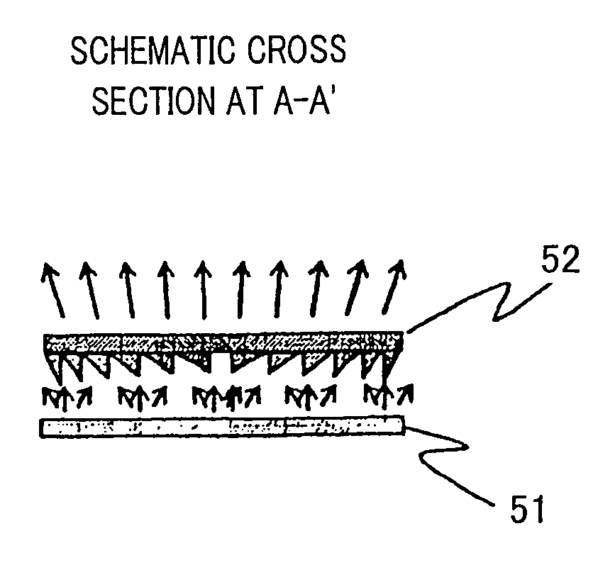
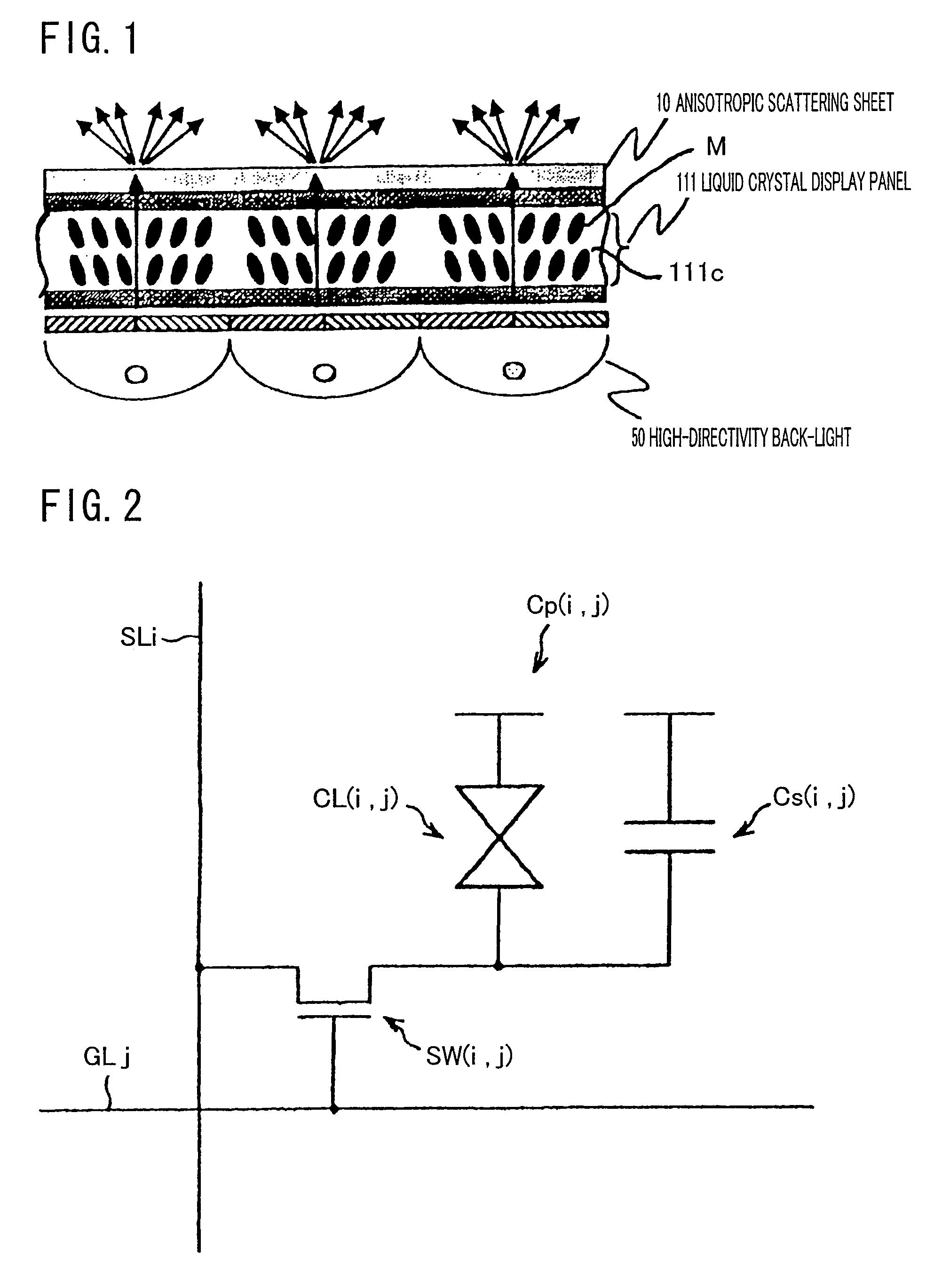
[0042]FIG. 1 is a cross section that schematically illustrates a structure of the liquid crystal display unit in the present invention.

[0043]As shown in FIG. 1, the liquid crystal display unit in the present invention includes a liquid crystal display panel 111, an anisotropic scattering sheet (a scattering-anisotropic optical element) 10, and a high-directivity back-light 50.

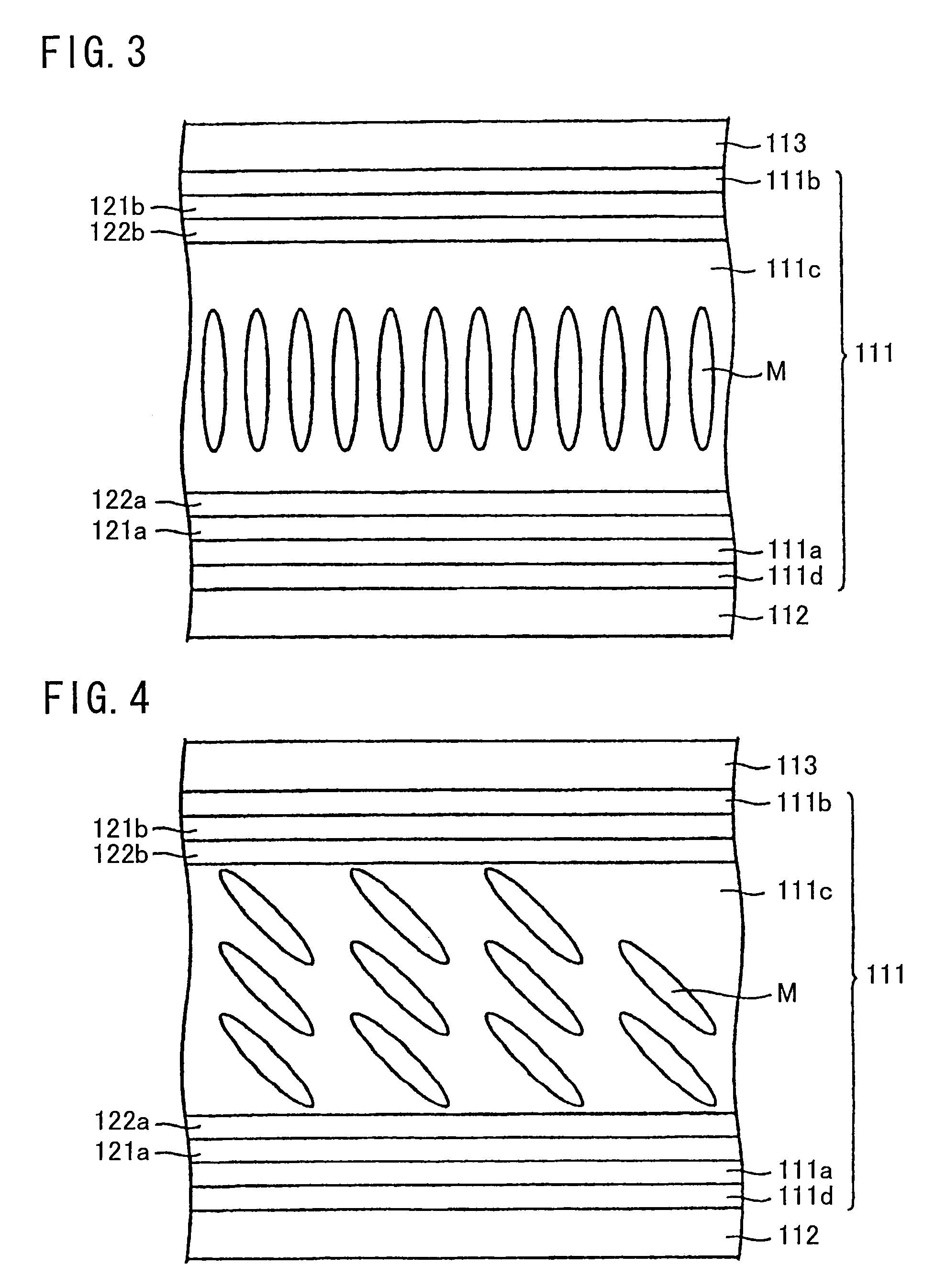
[0044]The liquid crystal display panel 111 includes a pair of substrates opposed to each other (a TFT substrate 111a and an opposed substrate 111b), and a liquid crystal layer 111c having negative dielectric anisotropic liquid crystal molecules M. The liquid crystal layer 111c is tightly held by the TFT substrate 111a and the opposed substrate 111b, and this liquid crystal layer 111c is oriented almost vertically to the surface of the TFT substrate 111a and...


PUM

PropertyMeasurementUnit
refractive indexaaaaaaaaaa
lengthaaaaaaaaaa
transparentaaaaaaaaaa

Abstract

A liquid crystal display unit is characterized by comprising a liquid crystal display panel, a back-light instrument for outputting light to the liquid crystal display panel, and a scattering-anisotropic optical instrument disposed on that side of the liquid crystal display panel which is opposite to the back-light instrument. The scattering-anisotropic optical instrument is so formed that the scattering intensity of light vertically entering the display screen of the liquid crystal panel is maximized. Therefore, the scattering-anisotropic optical instrument can scatter light vertically entering the display screen of the liquid crystal panel to allow a viewer to view a display screen from a wide range of viewing angles. In addition, because the unit does not scatter light entering obliquely, rather than vertically, a display screen but lets the light pass as it is, whitish appearance as is seen in an oblique-direction observation can be prevented. Therefore, whitish appearance can be prevented even if the back-light instrument does not output perfectly parallel light.

Description

BACKGROUND OF THE INVENTION[0001]1. Field of the Invention[0002]The present invention relates to a liquid crystal display unit used in a display device such as a computer, a television receiver, and many others.[0003]2. Description of the Related Art[0004]In a liquid crystal unit used as a television that reproduces moving image, demands for image quality, including a moving image response performance and a contrast, are high. A display unit that tightly holds a negative dielectric anisotropic liquid crystal layer between the substrates opposed to each other and that employs a liquid crystal display panel in which liquid crystal molecules are almost vertically oriented to the substrates when voltage is not applied to the liquid crystal molecules is characterized by its high contrast and high-speed response performance. However, the display unit has a problem of poor display quality. Specifically, because of the high dependency on a viewing angle, transmittance in an oblique directio...

Claims


Application Information

Patent Timeline
Patent Type & Authority Patents(United States)
IPC IPC(8): G02F1/1335G02B5/30G02F1/13357G02F1/139
CPCG02F1/133504G02F1/139
Inventor ISHIZUMI, TAKASHIYAMAHARA, MOTOHIRO
Owner SHARP KK
Why Eureka
Try Eureka