
Alignment system for observation instruments

Active Publication Date: 2008-06-03
CELESTRON ACQUISITION
View PDF53 Cites 13 Cited by
  • Summary
  • Abstract
  • Description
  • Claims
  • Application Information

AI Technical Summary

Problems solved by technology

For example, the drive mechanism for the equatorial mount can be a relatively complicated and expensive mechanism that cannot readily be installed by an average amateur astronomer.
Further, it is difficult to make small changes in the rate of rotation to maintain a fix on a planet or the moon with drive mechanisms that do not have variable drive rates.
The Alt-Az mount obviates the twisting of the fork tines that makes it so difficult to design the declination axle bearings of the equatorially mounted telescope.
However, for a beginner, the alignment process can be a big obstacle.
A beginner may not be able to locate or identify any of the stars to be able to align the telescope.
Thus, a beginner cannot point the telescope to a star and tell the telescope that it is pointed at a particular star.
In addition, this system is less accessible to beginning users with small telescopes because the system includes the added cost of an imaging system along with the cost for a processor that can support the processing needed for the images generated by the imaging system as well as the alignment procedure of the align system itself.
Further, certain environments can make locating bright stars difficult with a fully automated system.
For example, transient objects like airplanes can confuse the system as the warning strobes on the planes may fool it into identifying the plane as a “bright object.” Also, automated systems do not have awareness of—and therefore will not avoid scanning of—obstructed portions of the sky (e.g., portions of the sky blocked by trees, clouds, building, etc.).
A particularly problematic situation would be where a user wishes to perform an automated alignment from a location such as the balcony of a high-rise building.
Ironically, a fully automated approach reduces the educational aspect of setting up a telescope because, during the setup process performed by these automated systems, it is often not obvious where the telescope is pointing to acquire alignment objects and hence the user would not gain any insight into the night sky.
Even if the automated system included an imager, and a display is attached to it so as to display the images captured from the imager, the user still will not gain any sense for where the telescope is actually pointing.
For example, if the user is standing at a telescope that is pointing somewhere, it will be difficult for the user to tell which one of the stars in the sky at which the telescope is actually pointing—even if the display is displaying the star and the star's name.

Method used


Image

  • Alignment system for observation instruments
  • Alignment system for observation instruments
  • Alignment system for observation instruments

Examples


Embodiment Construction

[0013]The present invention provides an alignment system for aligning an optical instrument such as a telescope with the celestial coordinate system.

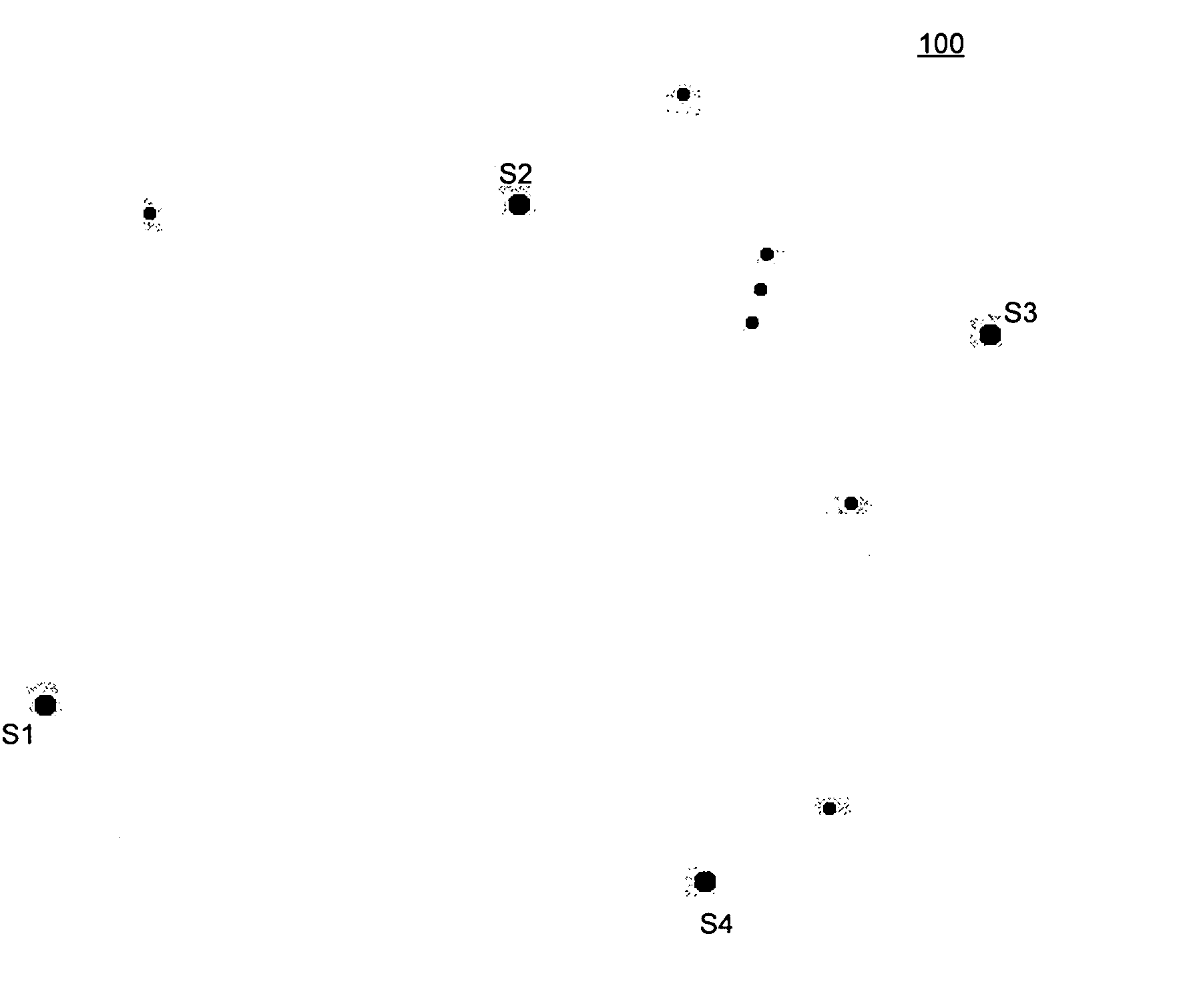
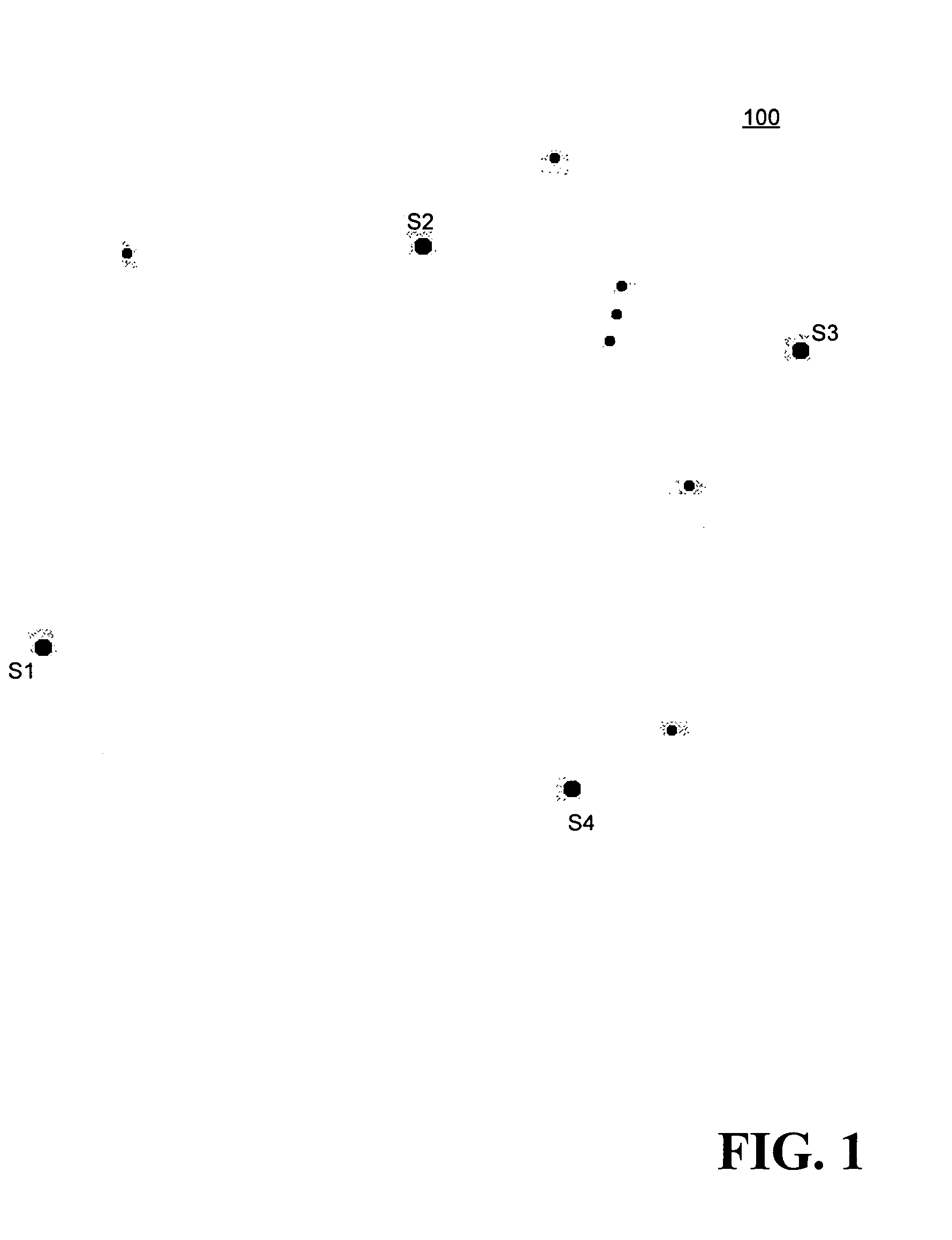
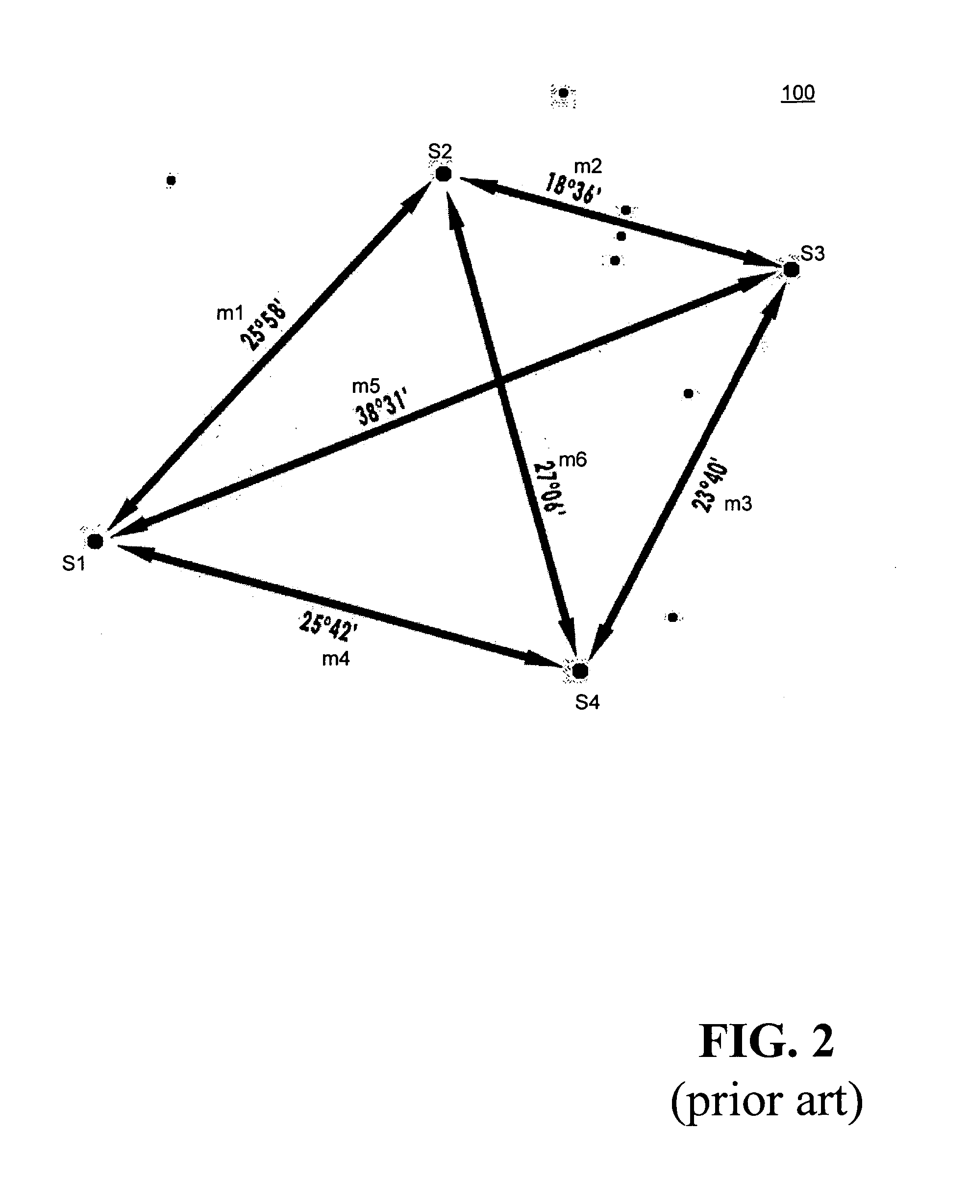
[0014]It is an object of the present invention to provide a method for aligning an optical instrument with respect to a celestial coordinate system, the optical instrument having a field of view and an optical instrument coordinate system, the celestial coordinate system having a plurality of objects each having celestial coordinates. The method includes the steps of receiving a plurality of captured optical instrument positions in the optical instrument coordinate system along with a plurality of associated capture times; calculating, for each associated capture time in the plurality of associated capture times, coordinates in the optical instrument coordinate system for the plurality of objects to create a plurality of calculated object positions for each associated capture time; and, determining, for each associated capture time, a m...


PUM


Abstract

A method and apparatus is disclosed for aligning an optical instrument with respect to a celestial coordinate system, the optical instrument having a field of view and an optical instrument coordinate system, the celestial coordinate system having a plurality of objects each having celestial coordinates. The method includes the steps of receiving a plurality of captured optical instrument positions in the optical instrument coordinate system along with a plurality of associated capture times; calculating, for each associated capture time in the plurality of associated capture times, coordinates in the optical instrument coordinate system for the plurality of objects to create a plurality of calculated object positions for each associated capture time; and, determining, for each associated capture time, a match for each captured optical instrument position in the plurality of captured optical instrument positions with the plurality of calculated object positions to create a list of actual alignment objects.

Description

FIELD OF THE INVENTION[0001]The present invention relates generally to telescopes and other observation instruments and, more particularly, it relates to an alignment system for observation instruments.BACKGROUND OF THE INVENTION[0002]The alignment and determination of an initial orientation is critical to the operation of any observation instrument, such as a telescope. Traditionally, a telescope is aligned by a two-star alignment process, where the telescope is aligned to a first star, and then the telescope is aligned to a second star. One of the requirements of the two-star alignment system is that the stars must be known.[0003]There are numerous designs for mounting astronomical telescopes, including equatorial and altitude-azimuth (altazimuth or Alt-Az) mounts. A mount is said to be equatorial if one of its two axes can be made parallel with the Earth's axis of rotation. The equatorial mount includes a rotatable polar shaft (to be made parallel to the Earth's axis of rotation)...

Claims


Application Information

Patent Timeline
IPC IPC(8): G01B11/26
CPCG01B21/26G02B23/16
Inventor HEDRICK, RICHARD L.PAQUETTE, ANDRE
Owner CELESTRON ACQUISITION
Learn More