Wave plate and associated method

a technology of wave plate and associated method, which is applied in the field of wave plate, can solve the problems affecting the design of optical systems that employ polarization wave plate, and changing the retardation amount of the conventional wave plate, etc., and achieves the effect of reducing the angle sensitivity of the wave pla

Active Publication Date: 2008-06-03
THE BOEING CO
View PDF9 Cites 8 Cited by
  • Summary
  • Abstract
  • Description
  • Claims
  • Application Information

AI Technical Summary

Benefits of technology

[0009]Embodiments of the invention address the above needs and achieve other advantages by providing a wave plate that is capable of achieving a desired retardance, while reducing the angular sensitivity of the wave plate. The wave plate includes at least one layer of positive uniaxial crystal and at least one layer of negative uniaxial crystal. The fast axes of each of the positive and negative layers of uniaxial crystal may be aligned such that the retardance of the layers add together or subtract from one another. In addition, the thicknesses of each of the layers of uniaxial crystal may be selected to reduce or eliminate the angular sensitivity of the wave plate. As a result, the wave plate may have more practical thicknesses without suffering a significant change in retardance resulting from changes in the angle of incident optical signals.
[0010]In one embodiment of the present invention, a wave plate is provided. The wave plate could be a multi-order wave plate. The wave plate includes a plurality of layers of uniaxial crystal that are positioned such that a respective fast axis of at least a pair of layers is substantially commonly aligned or substantially perpendicular, thereby causing a retardance of the pair of uniaxial crystals to be cumulative or at least partially cancel one another.

Problems solved by technology

The design of optical systems that employ polarization wave plates can be unduly limited by changes in wave plate performance with angle of incidence of the incoming signals.
However, the amount of retardation of a conventional wave plate changes as the angle of the optical signals passing through it changes.
This effect can sometimes be made small by using a true zero-order wave plate, but these wave plates are extremely thin and delicate if made of conventional birefringent crystals.
Multi-order or compound pseudo zero-order wave plates are made of crystals with more reasonable (practical) thicknesses, but the range of angles they can be used over is undesirably limited by the angular dependence of their retardance.

Method used


Image

  • Wave plate and associated method
  • Wave plate and associated method
  • Wave plate and associated method

Examples


Embodiment Construction

[0018]The present invention now will be described more fully hereinafter with reference to the accompanying drawings, in which some, but not all embodiments of the invention are shown. Indeed, the invention may be embodied in many different forms and should not be construed as limited to the embodiments set forth herein; rather, these embodiments are provided so that this disclosure will satisfy applicable legal requirements. Like numbers refer to like elements throughout.

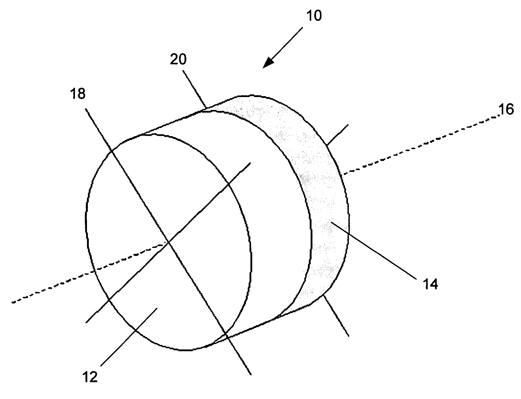
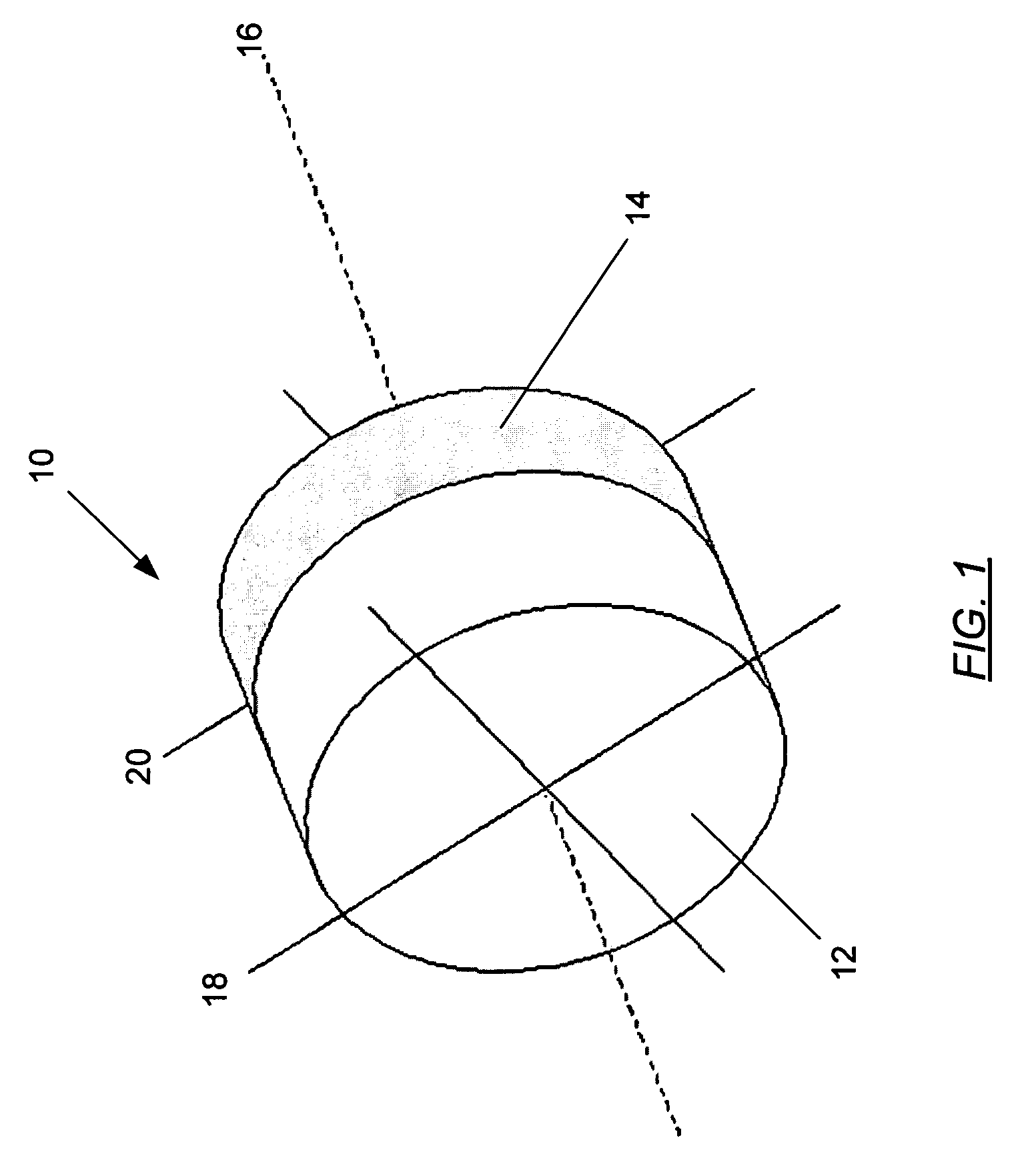
[0019]With reference to FIG. 1, there is shown a wave plate 10. The wave plate 10 generally includes a positive layer of uniaxial crystal 12 and a negative layer of uniaxial crystal 14. In the embodiment shown, the fast axes 18 and 20 of respective positive 12 and negative 14 layers are substantially commonly aligned with one another. As a result, the positive 12 and negative 14 layers are aligned such that the retardance of each of the layers adds together. In addition, the thicknesses of the positive 12 and negat...


PUM


Abstract

An improved wave plate and associated method are provided. The wave plate includes a plurality of layers of uniaxial crystal including at least one layer of positive uniaxial crystal and at least one layer of negative uniaxial crystal. The thicknesses of the layers are configured to achieve both a desired retardance and an insensitivity to angle of incidence.

Description

FEDERALLY SPONSORED RESEARCH OR DEVELOPMENT[0001]This invention was made with Government support under Contract No. FA9453-04-C-0050 awarded by the U.S. Air Force. The Government has certain rights in this invention.BACKGROUND OF THE INVENTION[0002]1. Field of the Invention[0003]The present invention is related to wave plates and, more particularly, to wave plates including uniaxial crystals for achieving an insensitivity to angle of incidence.[0004]2. Description of Related Art[0005]Wave plates are devices that alter the polarization of optical signals when optical signals pass through the wave plate. Birefringent materials, which are refractive materials typically used for wave plates, exhibit an anisotropic index of refraction or velocity of propagation of optical signals passing therethrough. The index of refraction varies for different polarizations, and the relative amount of phase shift of the polarized optical signals through the birefringent material is generally referred t...

Claims


Application Information

Patent Timeline
Patent Type & Authority Patents(United States)
IPC IPC(8): G02B5/30
CPCG02B5/3083
Inventor HULSEY, DANIEL E.
Owner THE BOEING CO
Why Eureka
Try Eureka