High efficiency monochromatic X-ray source using an optical undulator

a monochromatic x-ray source and undulator technology, applied in the direction of x-ray tubes, irradiation devices, nuclear engineering, etc., can solve the problems of inability to meet the requirements of a single wavelength, etc., to achieve the effect of reducing the energy required for operation of such sources, reducing the size, cost and operating expense, and reducing the size of the a monochromatic x-ray source undulator-based x-ray source monochromatic x-ray source and monochromatic x-ray source and optical undulator-based x-ray source, high efficiency, a high efficiency of x-ray source, a high efficiency of x-rays and other electromagnetic radiation production field, which is applied in the field of electromagnetic radiation radiation radiation radiation radiation x-ray radiation radiation radiation x-ray radiation x-ray radiation x-ray radiation x-ray radiation x-ray radiation x-ray radiation x-ray radiation x-ray

Inactive Publication Date: 2008-06-03
MADEY JOHN M J
View PDF6 Cites 21 Cited by
  • Summary
  • Abstract
  • Description
  • Claims
  • Application Information

AI Technical Summary

Benefits of technology

[0013]Equally important, the electron energy required for operation of such sources is reduced by the square root of the same factor making possible very substantial reductions in size, cost and operating expense. Finally, in contrast to short wavelength radiation sources based on the use of magnetic undulators, the ability to alter the wavelength and format of the optical pulse train comprising the optical undulator on successive radiation intervals makes possible a level of flexibility in the generation of the single and multi-color x-ray pulses required for use unattainable through use of a conventional magnetic undulator.
[0014]The optical properties of near-concentric optical cavities make possible the generation of the intense optical pulses needed for operation of the invention by integrating the optical power injected into the cavity from one or more low power pump lasers, and focusing that accumulated energy to a small spot in the vacuum within the cavity. By appropriate design, the peak optical power density and fluence at the interior surfaces of the cavity can be reduced by diffraction to a level consistent with the peak power damage thresholds of those surfaces. The fluence and average optical power incident on these surfaces can be further kept below the integrated pulse and average power damage thresholds by limiting the interval of time over which the pump laser(s) inject optical power into the cavity.
[0015]As a matter of terminology, it is convenient to refer to the individual optical pulses injected into or stored within the optical cavity as optical micropulses, and to refer to the spaced intervals during which such optical micropulses are injected into the optical cavity as the radiation intervals. The laser radiation incident on the cavity thus has a hierarchical pulse structure that is characterized by two disparate time scales, namely that of the radiation intervals and that of the micropulses. As will be described below, the system and method are configured so that optical micropulses injected into the cavity coherently reinforce optical micropulses circulating in the cavity, thus causing the amplitude of a given circulating optical micropulse to increase.
[0029]By incorporating an optical undulator with normalized vector potentials of the order of an˜0.1 and greater but with a spatial period of the order of a micron, the invention described herein can be operated with both undulators and e-beam accelerators of dramatically reduced size and cost, permitting high performance ultraviolet and x-ray light sources to be constructed and operated at a fraction of the cost heretofore possible.

Problems solved by technology

The extended length of the undulators used for such systems, together with the size, cost and complexity of the accelerator systems needed to generate the high energy, high power electron beams required for operation, have made such light sources both physically large and expensive.
However, the concept of Compton scattering as described in the literature (Heitler 1960) is applicable only when the mechanism can be described as the scattering of single photons, and is no longer valid when the electric and magnetic fields of the incident electromagnetic wave are strong enough to induce transverse velocities approaching the speed of light, e.g., when their normalized vector potential approaches unity.
Given this restriction to low field amplitudes and the dependence of the radiated power on the square of the field amplitude, electron beam-based inverse-Compton light sources have simply not proven competitive with undulator-based light sources to date.

Method used


Image

  • High efficiency monochromatic X-ray source using an optical undulator
  • High efficiency monochromatic X-ray source using an optical undulator
  • High efficiency monochromatic X-ray source using an optical undulator

Examples


Embodiment Construction

Basic Configuration and Operation

[0044]In brief, embodiments of the present invention enable the generation of x-rays and other energetic electromagnetic radiation (short wavelengths including ultraviolet and gamma rays). These embodiments can provide the bright, near-monochromatic, high average-power and peak-power x-ray beams required for x-ray crystallography, medical radiography and radiotherapy and other x-ray and gamma ray imaging systems, and for research in nuclear and high energy physics.

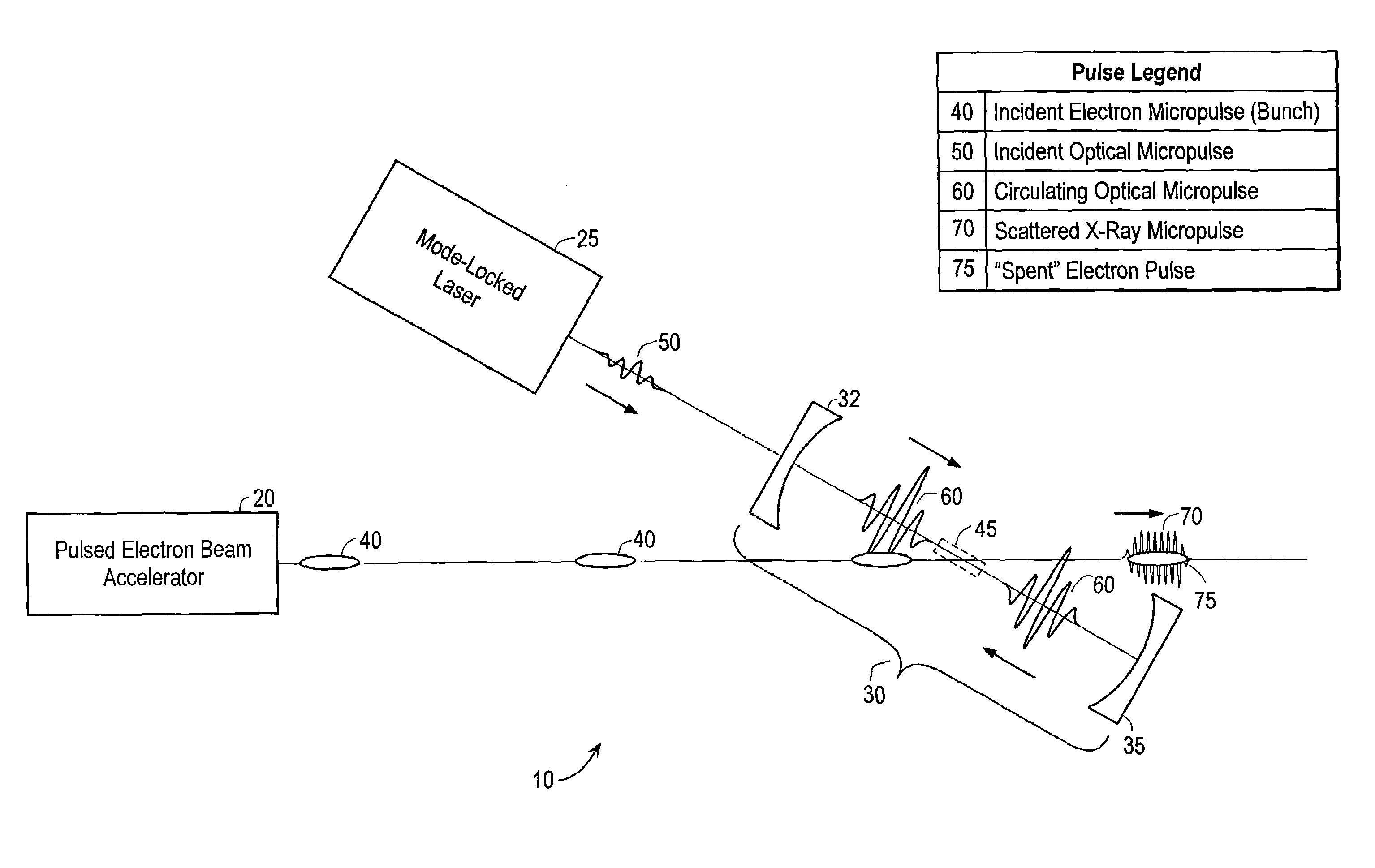
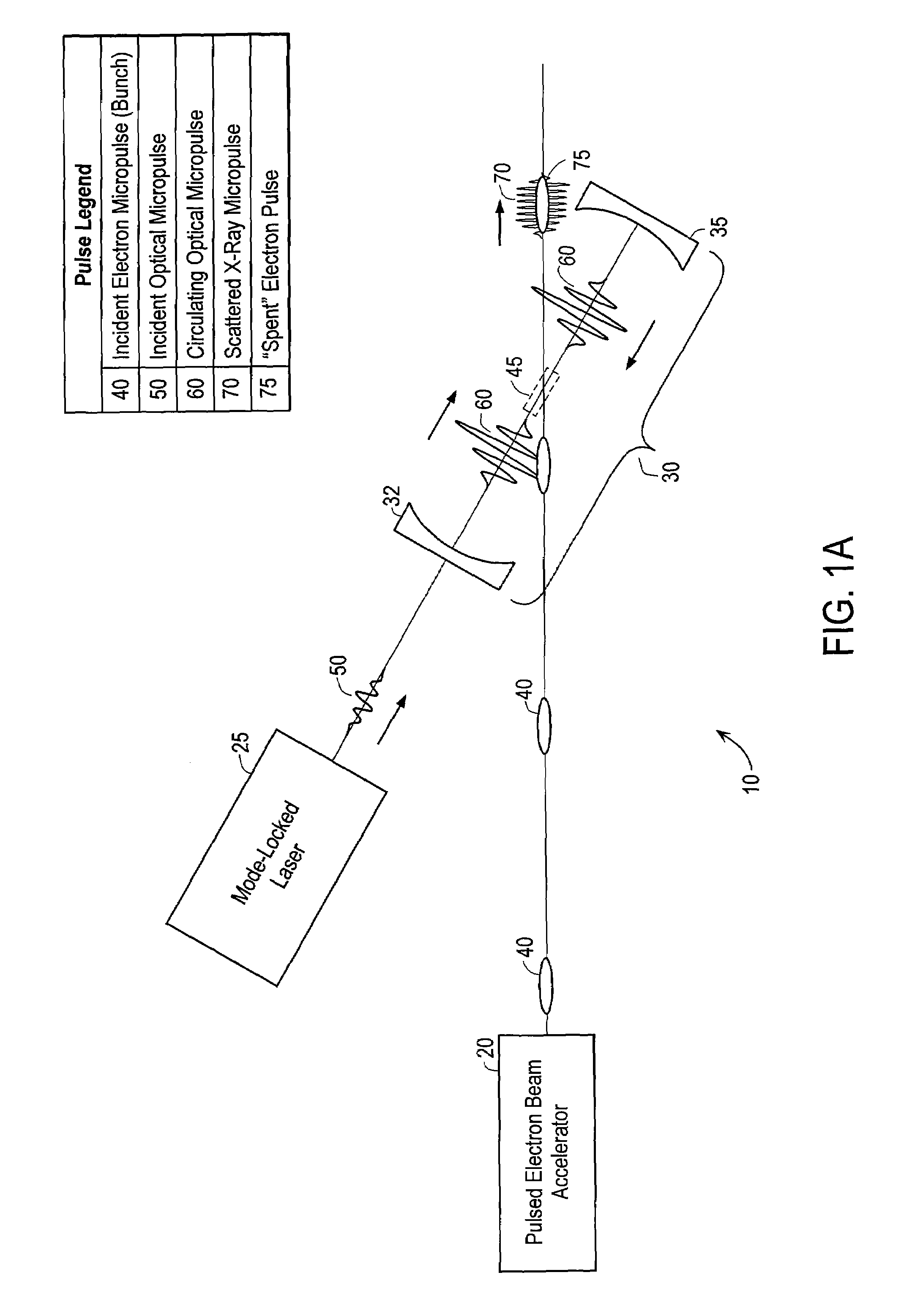
[0045]FIG. 1A is a high-level schematic of the primary elements of a representative system 10 according to an embodiment of the present invention. The primary elements of the system include an electron source such as a pulsed electron beam accelerator 20, a pulsed light source such as a mode-locked pump laser 25 (or multiple pump lasers), and an optical cavity 30, which is operated as an optical resonator. Cavity 30 is shown schematically as including opposed concave mirrors 32 and 35. In b...


PUM


Abstract

A method of generating energetic electromagnetic radiation comprises, during each of a plurality of separated radiation intervals, injecting laser radiation of a given wavelength into an optical cavity that is characterized by a round-trip transit time (RTTT) for radiation of that given wavelength. At least some radiation intervals are defined by one or more optical macropulses, at least one optical macropulse gives rise to an associated circulating optical micropulse that is coherently reinforced by subsequent optical micropulses in the optical macropulse and the electric field amplitude of the circulating optical micropulse at any given position in the cavity reaches a maximum value during the radiation interval.

Description

CROSS-REFERENCE TO RELATED APPLICATION[0001]This application claims the benefit of 35 U.S.C. § 119(e) of U.S. Patent Application No. 60 / 687,014, filed Jun. 2, 2005, the entire disclosure of which is incorporated by reference.BACKGROUND OF THE INVENTION[0002]The present invention relates generally to the production of x-rays and other energetic electromagnetic radiation (short wavelengths), and more specifically to techniques for interacting relativistic electrons with electromagnetic radiation having relatively long wavelengths to generate electromagnetic short-wavelength radiation.[0003]The unique ability of electron beam-based sources of electromagnetic radiation employing undulators to generate intense, near monochromatic, forward peaked beams of radiation have made undulators critical components of advanced light sources such as second and third-generation synchrotron radiation sources and free-electron lasers. There are therefore many references to undulator technology and the ...

Claims


Application Information

Patent Timeline
Patent Type & Authority Patents(United States)
IPC IPC(8): H05G2/00
CPCH05G2/00G21G4/00H01J35/00G21K5/00
Inventor MADEY, JOHN M. J.SZARMES, ERIC B.
Owner MADEY JOHN M J
Why Eureka
Try Eureka