Electrode Manufacturing Method Comprising Cleaning Step Using Laser, Electrode Manufactured By Method, and Secondary Battery Comprising Same

a manufacturing method and electrode technology, applied in the direction of sustainable manufacturing/processing, battery components, battery cells, etc., can solve the problems of reducing the capacity of the electrode, deteriorating the performance of the battery cell, and reducing the safety of the secondary battery, so as to achieve a significant reduction of the sliding generation level in the boundary region

Pending Publication Date: 2022-05-12
LG ENERGY SOLUTION LTD
View PDF0 Cites 0 Cited by
  • Summary
  • Abstract
  • Description
  • Claims
  • Application Information

AI Technical Summary

Benefits of technology

[0019]According to the method for manufacturing an electrode according to the present invention, a mismatch of the electrode mixture layer can be prevented and the sliding generation level in the boundary region can be significantly reduced through a cleaning step which is performed so that a line of irradiating laser to the top-coated electrode mixture layer of the electrode current collector and a line of irradiating laser to the back-coated electrode mixture layer of the electrode current collector correspond to each other in a direction perpendicular to that of the electrode current collector.

Problems solved by technology

Such a mismatch region (DM) decreases the capacity of the electrode and decreases the safety when applied to a secondary battery.
In the case that the second electrode 20 is a negative electrode, as the loading amount of the positive electrode for the negative electrode becomes greater than a predetermined amount, lithium precipitation occurs in the region, which deteriorates the performance of the battery cell.

Method used


Image

  • Electrode Manufacturing Method Comprising Cleaning Step Using Laser, Electrode Manufactured By Method, and Secondary Battery Comprising Same
  • Electrode Manufacturing Method Comprising Cleaning Step Using Laser, Electrode Manufactured By Method, and Secondary Battery Comprising Same
  • Electrode Manufacturing Method Comprising Cleaning Step Using Laser, Electrode Manufactured By Method, and Secondary Battery Comprising Same

Examples


first embodiment

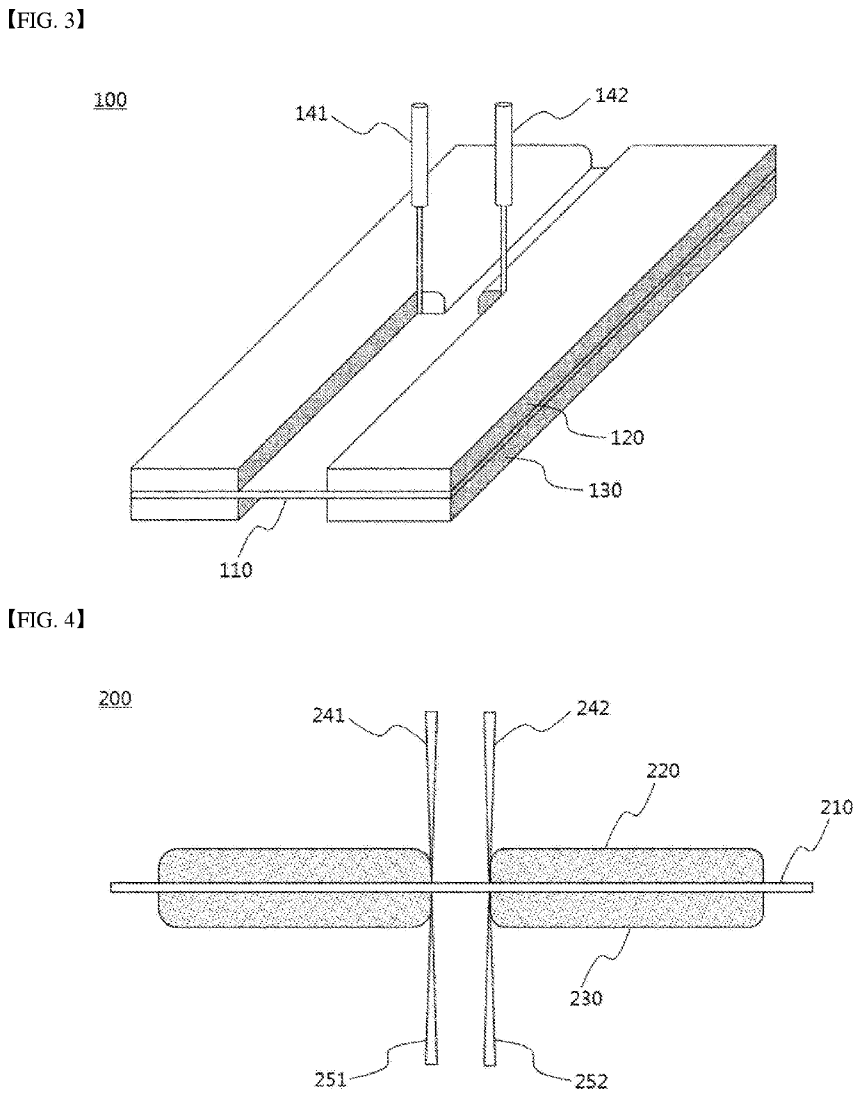
[0054]FIG. 3 is a schematic diagram illustrating an electrode manufacturing process according to an embodiment of the present invention. Referring to FIG. 3, an electrode according to the present invention has a structure in which a top-coated electrode mixture layer 120 and a back-coated electrode mixture layer 130 are formed on opposite surfaces of a current collector 110. In the present invention, the electrode is manufactured through a step 100 of cleaning the end of the coated part through laser irradiations 141 and 142 along the boundary line of the coated part contacting the non-coated part. Generation of a sliding phenomenon at the end of the electrode mixture layers 120 and 130 is prevented through the laser irradiations 141 and 142.

[0055]FIG. 4 is a cross-sectional view illustrating an electrode manufacturing process according to an embodiment of the present invention. Referring to FIG. 4, the cleaning step 200 of the present invention is performed so that lines irradiatin...

second embodiment

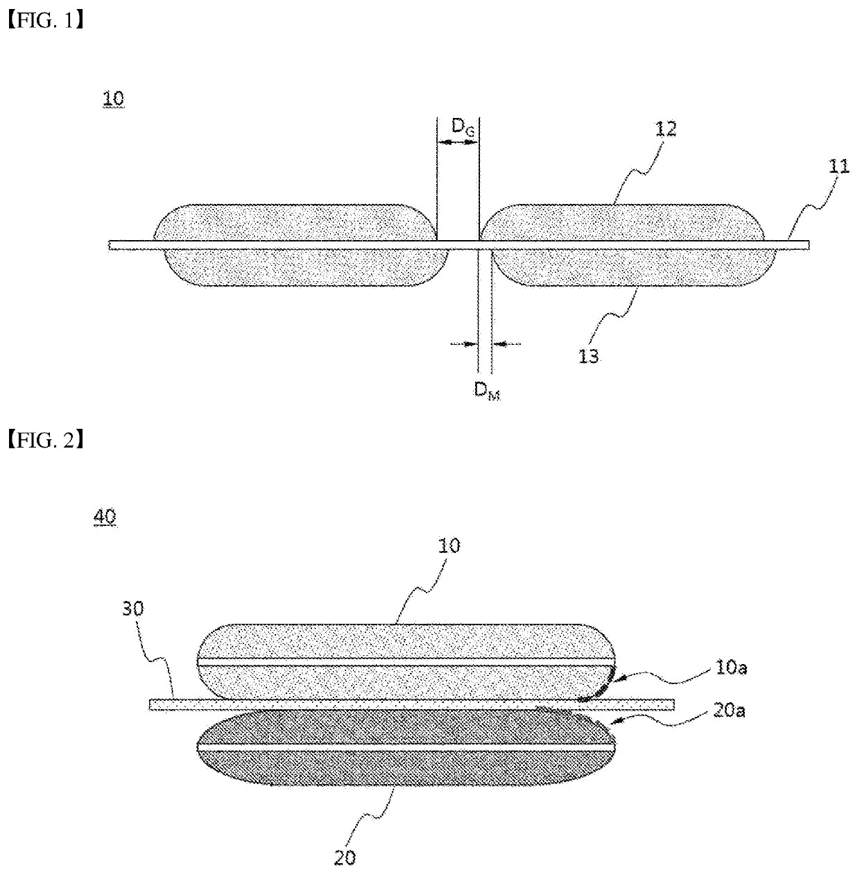
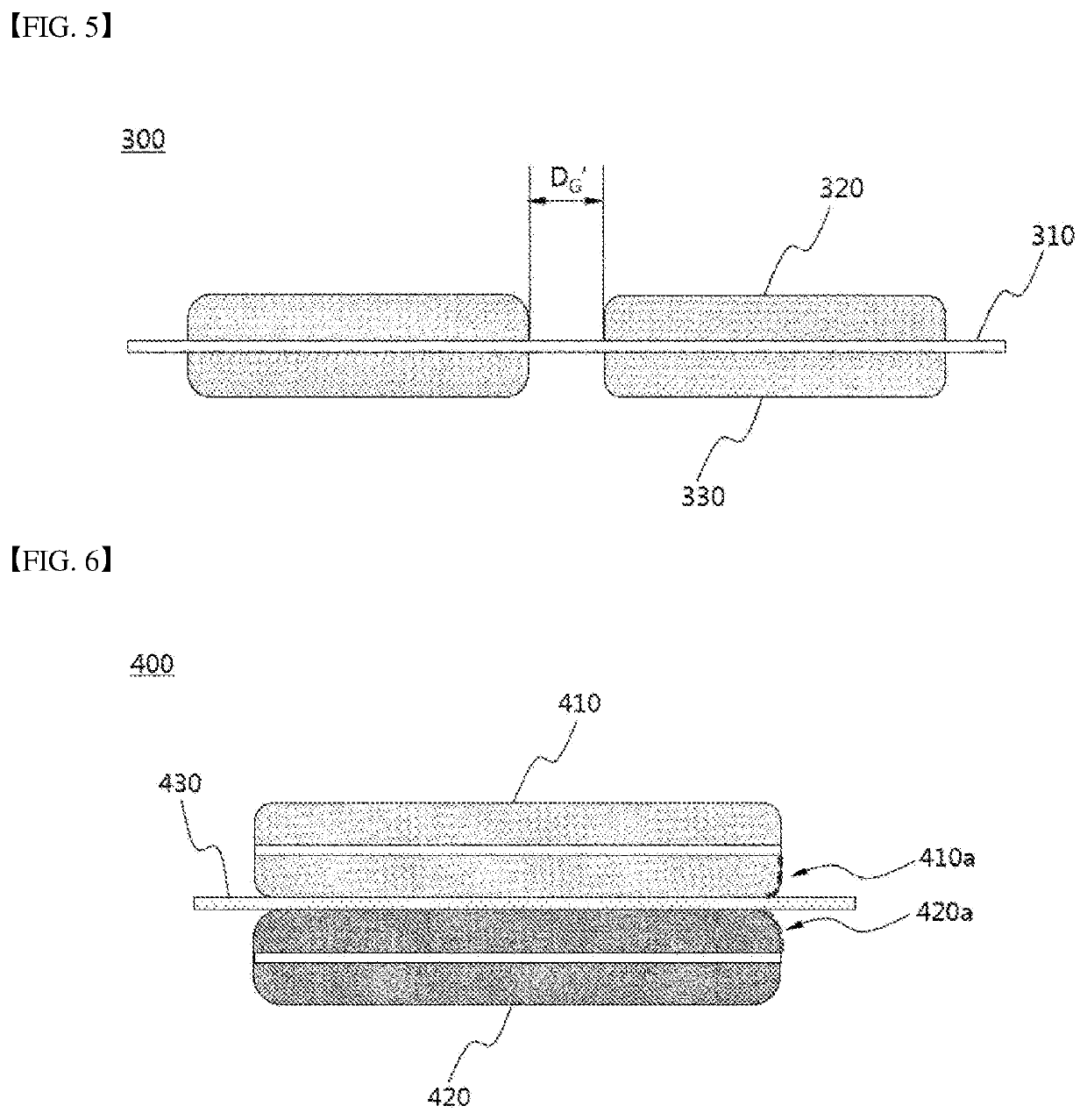
[0056]FIG. 5 is a cross-sectional view illustrating a structure of an electrode according to an embodiment of the present invention. Referring to FIG. 5, a first electrode 300 has a structure in which a top-coated electrode mixture layer 320 and a back-coated electrode mixture layer 330 are formed on opposite surfaces of a current collector 310. Further, each of the electrode mixture layers 320 and 330 includes a coated part, on which an electrode mixture layer has been applied, and a non-coated part. A separation distance between coated parts having the electrode mixture layer formed thereon means a width (DG′) of the non-coated part. In the present invention, in the cleaning step through laser irradiation, lines irradiating laser to the top-coated electrode mixture layer 320 and the back-coated electrode mixture layer 330 of the electrode current collector 310 correspond to each other in a direction that is perpendicular to the electrode current collector 310. Hence, a mismatch re...

third embodiment

[0057]FIG. 6 is a cross-sectional view illustrating a laminated structure of an electrode assembly prepared according to an embodiment of the present invention. Referring to FIG. 6, the electrode assembly 400 has a structure in which the first electrode 410 and the second electrode 420 are formed on opposite surfaces on the basis of the separator 430. Different sliding levels 410a and 420a are generally shown in the boundary region of the electrode mixture layer in each process of manufacturing the first and second electrodes 410 and 420. However, in the present invention, the electrode mixture layer of the first and second electrodes 410 and 420 shows the same or similar sliding levels 410a and 420a in the boundary region through the cleaning step by laser irradiation. As such, the loading ratio of the positive electrode mixture layer corresponding to the negative electrode mixture layer is maintained equally even in the boundary region of the electrode mixture layer.

[0058]The abov...


PUM

PropertyMeasurementUnit
formation angleaaaaaaaaaa
weight ratioaaaaaaaaaa

Abstract

The present technology relates to an electrode manufacturing method, an electrode manufactured by the method, and a secondary battery comprising same, the electrode manufacturing method comprising a cleaning step performed by laser irradiation, in lines corresponding to each other in a direction perpendicular to an electrode current collector, onto a top-coated electrode mixture layer and a back-coated electrode mixture layer of the electrode current collector, and may prevent a mismatch of the electrode mixture layers and may significantly reduce the degree of sliding occurrence at the boundary region.

Description

TECHNICAL FIELD[0001]This application claims the benefit of priority based on Korean Patent Application No. 10-2020-00014827, filed on Feb. 7, 2020, and the entire contents of the Korean patent application are incorporated herein by reference.[0002]The present invention relates to a method for manufacturing an electrode including a cleaning step by laser, an electrode manufactured by the method, and a secondary battery including the same.BACKGROUND ART[0003]With the increase in technology development and demand for mobile devices, the demand for secondary batteries is also rapidly increasing. Among them, lithium secondary batteries are widely used as an energy source for various electronic products as well as various mobile devices because of their high energy density and high operating voltage and excellent storage and lifetime characteristics.[0004]In addition, the secondary battery has attracted attention as an energy source of an electric vehicle, a hybrid electric vehicle, etc....

Claims


Application Information

Patent Timeline
Patent Type & Authority Applications(United States)
IPC IPC(8): H01M4/36H01M4/04H01M4/38H01M4/583H01M4/66
CPCH01M4/366H01M4/0404H01M4/364H01M2004/027H01M4/583H01M4/663H01M4/386H01M4/04H01M4/139H01M10/052B23K26/362B23K26/352H01M2220/30H01M10/0404Y02E60/10B23K26/351B23K26/40B23K2101/36H01M10/0413H01M10/0587Y02P70/50H01M2004/021H01M2010/4292H01M2004/028
Inventor CHOI, HYOUNG SIKHUH, JUN HYEAKKIM, JEOUNG SOOKIM, KI WOONGAN, IN GUSUNG, KI EUN
Owner LG ENERGY SOLUTION LTD
Why Eureka
Try Eureka