
Cyclic transmit power adjustment scheme

a transmission power and cyclic technology, applied in the field of radio frequency communications, can solve the problems of imposing significant penalties on system capacity and throughput, insufficient coverage at the edge of cells, and high implementation costs, so as to minimize the impact of interference, efficiently support dynamic needs, and minimize the effect of interferen

Active Publication Date: 2008-06-03
MALIKIE INNOVATIONS LTD
View PDF12 Cites 48 Cited by
  • Summary
  • Abstract
  • Description
  • Claims
  • Application Information

AI Technical Summary

Benefits of technology

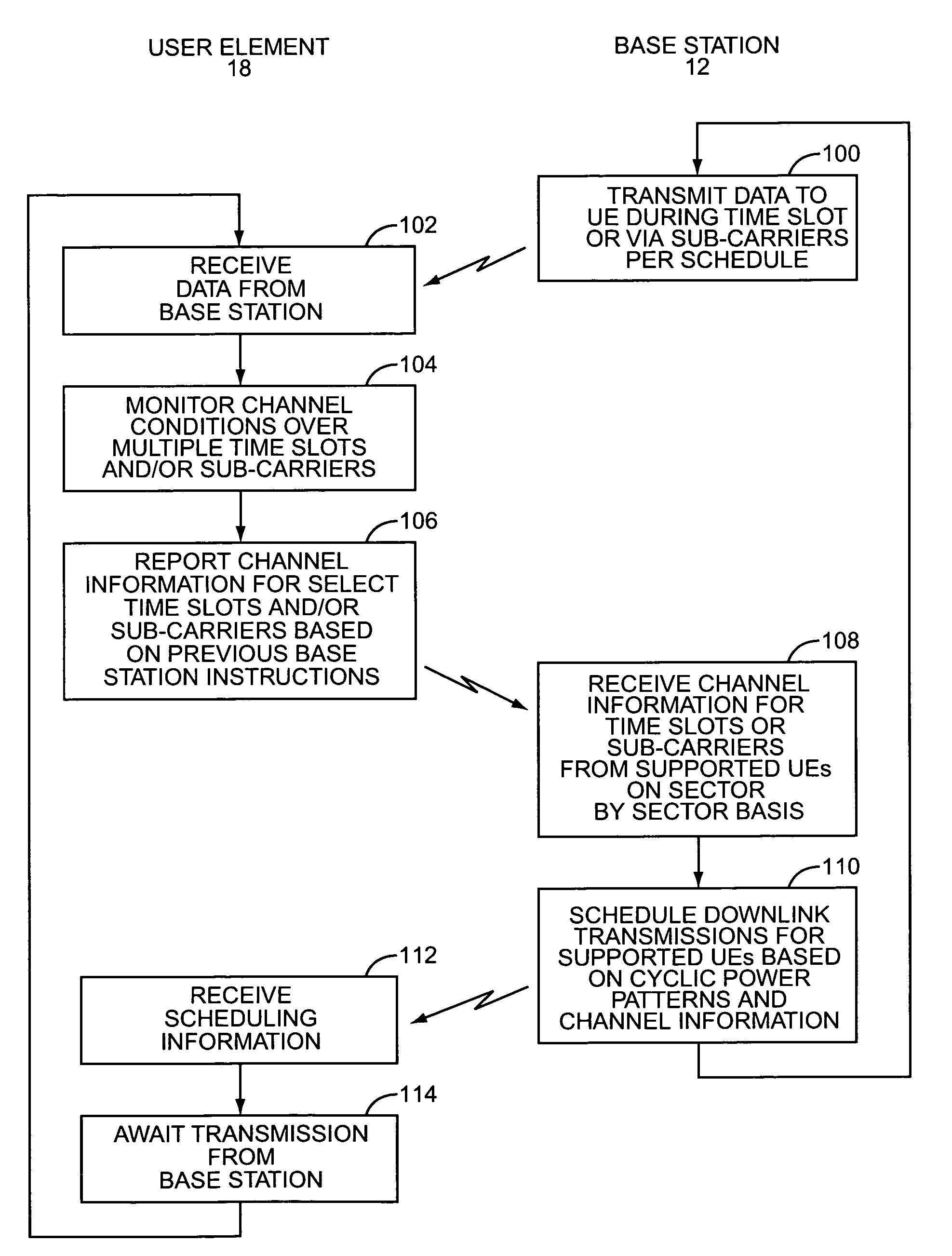
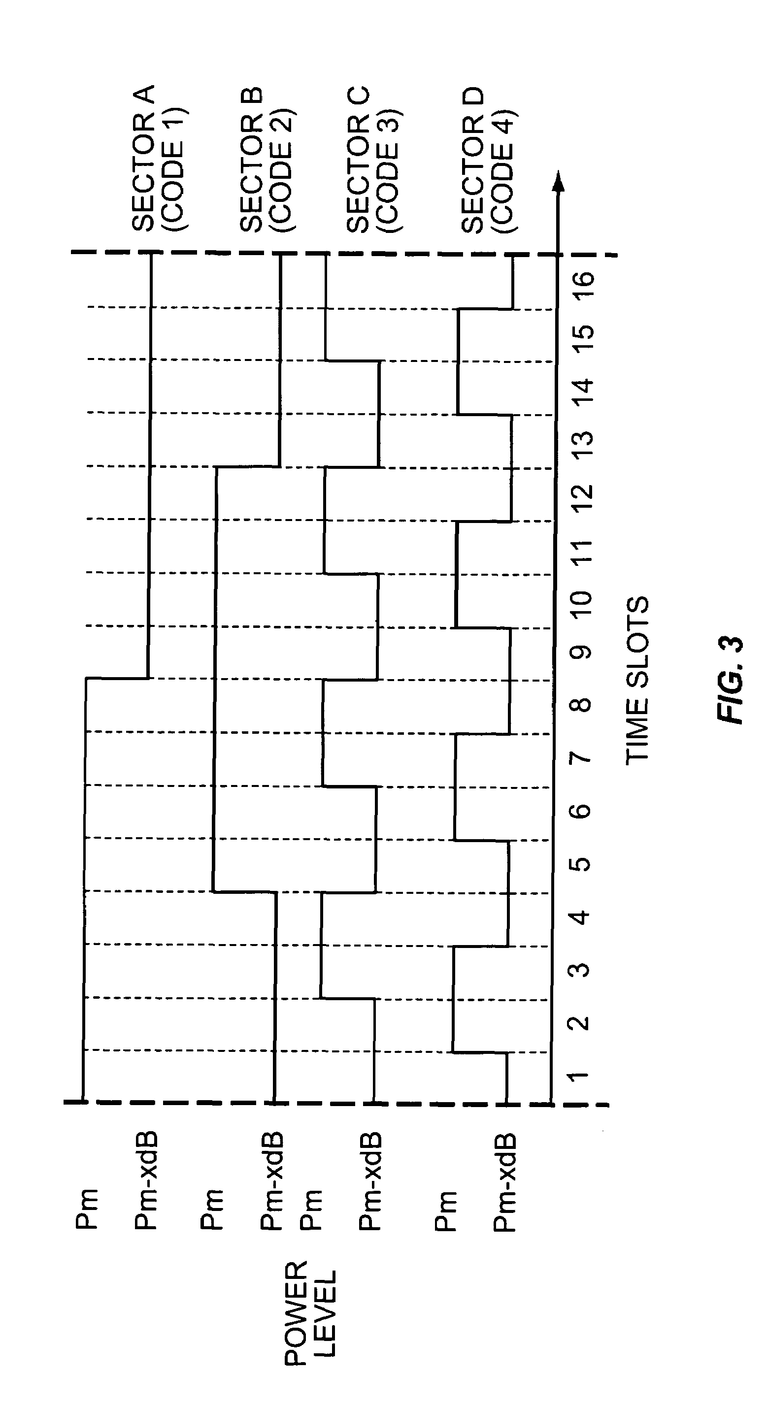
[0006]The present invention provides cyclic power changing patterns for transmissions in different sectors of a cellular system. The cyclic power changing patterns essentially define unique patterns in which transmission power levels change over a period of time slots or within a group of sub-carriers. Each sector has a unique pattern, so that interference information monitored by the user elements, which are supported by base stations, is indicative of the interference contributions from adjacent sectors. Based on these interference contributions and the cyclic power changing patterns associated with these sectors, the base stations can schedule transmissions to the user elements during time slots or in sub-carriers to minimize the impact of interference from the adjacent sectors and to efficiently support dynamic needs of the individual user data packets according to quality of service requirements. Scheduling does not necessarily have to minimize the impact of interference for a given user element, but the base stations can schedule data to all of the user elements being serviced to increase overall system performance, such as system capacity, per user throughput rates, and quality of service levels. A particular user experiences different levels of signal quality at different time intervals or sub-carriers because of the artificial channel condition changes created by the transmit power changes of the sectors. This allows scheduling to dynamically select the most efficient time slot for a user according to quality of service requirements and temporal data transmission needs, which increase overall throughput as well as per user throughput.

Problems solved by technology

Unfortunately, these techniques generally provide insufficient coverage at the edge of cells and impose significant penalties on system capacity and throughput, or are very costly and complex to implement.

Method used


Image

  • Cyclic transmit power adjustment scheme
  • Cyclic transmit power adjustment scheme
  • Cyclic transmit power adjustment scheme

Examples


Embodiment Construction

[0022]The embodiments set forth below represent the necessary information to enable those skilled in the art to practice the invention and illustrate the best mode of practicing the invention. Upon reading the following description in light of the accompanying drawing figures, those skilled in the art will understand the concepts of the invention and will recognize applications of these concepts not particularly addressed herein. It should be understood that these concepts and applications fall within the scope of the disclosure and the accompanying claims.

[0023]The present invention provides for distinct power change patterns for sectors 16 that are adjacent to one another in the same and separate cells 14. The cyclic power change patterns may be associated with transmission time slots, sub-carriers in an orthogonal frequency division multiplex (OFDM) spectrum, or a combination thereof. The cyclic power change patterns define pre-defined power levels at which communications will be...


PUM


Abstract

The present invention provides cyclic power changing patterns for transmissions in different sectors of a cellular system. The cyclic power changing patterns define unique patterns in which transmission power levels change over a period of time slots or within a group of sub-carriers. Each sector has a unique pattern, so that interference information monitored by the user elements, which are supported by base stations, are indicative of the interference contributions from adjacent sectors. Based on these interference contributions and the cyclic power changing patterns associated with these sectors, the base stations can schedule transmissions to the user elements during time slots or in sub-carriers to minimize the impact of interference from the adjacent sectors and to efficiently support dynamic needs of the individual user data packets according to QoS requirements.

Description

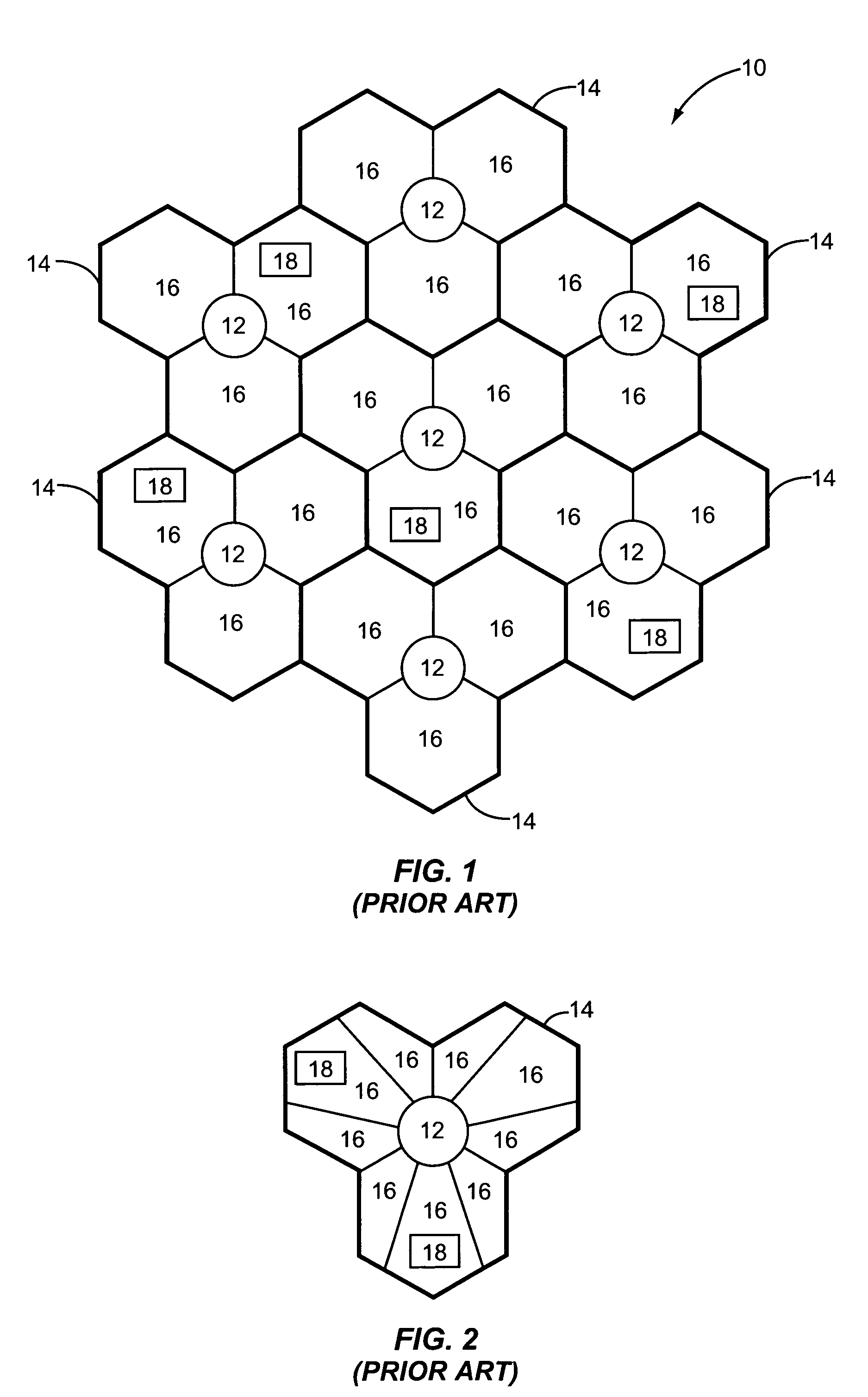
[0001]The present invention claims the benefit of U.S. provisional application Ser. No. 60 / 472,380 filed May 21, 2003 entitled CYCLIC TRANSMIT POWER ADJUSTMENT SCHEME, the disclosure of which is incorporated herein by reference in its entirety.FIELD OF THE INVENTION[0002]The present invention relates to radio frequency communications, and in particular to providing cyclic power control patterns for multiple sectors.BACKGROUND OF THE INVENTION[0003]As illustrated in FIG. 1, a cellular communication network 10 is supported by numerous base stations 12, which are capable of facilitating wireless communications throughout corresponding cells 14. Generally, each cell 14 is divided into numerous sectors 16, wherein the base stations 12 will have dedicated transmit and receive capabilities for each sector 16. A base station 12 may provide any number of sectors 16 to form a cell 14. For example, there are three sectors 16 forming each cell in FIG. 1, and nine sectors 16 forming the cell 14 ...

Claims


Application Information

Patent Timeline
IPC IPC(8): H04B7/00H04Q7/20H04W52/36H04W72/12
CPCH04L1/0026H04L5/0032H04L5/0037H04L5/006H04B17/345H04L5/0094H04B17/24H04B17/309H04L5/0064H04L5/0007H04L5/0023H04W52/367H04W72/1226H04W72/54
Inventor SENARATH, GAMINICHEONG, YOON CHAEPERIYALWAR, SHALINI
Owner MALIKIE INNOVATIONS LTD
Learn More