Hydraulic transaxle and vehicle comprising it

Active Publication Date: 2008-06-10
KANZAKI KOKYUKOKI MFG
View PDF22 Cites 36 Cited by
  • Summary
  • Abstract
  • Description
  • Claims
  • Application Information

AI Technical Summary

Benefits of technology

[0014]A second object of the present invention is to provide a vehicle having a pair of first and second transaxles: the first transaxle incorporating a first hydraulic motor, a first drive wheel and a first deceleration gearing interposed between the first hydraulic motor and the first drive wheel; and the second transaxle incorporating a second hydraulic motor, a second drive wheel and a second deceleration gearing interposed between the second hydraulic motor and the second drive wheel, a rotary speed of the second drive wheel being equal to a rotary speed of the first drive wheel during straight traveling of the vehicle, and the rotary speed of the second drive wheel being larger than the rotary speed of the first drive wheel during turning of the vehicle, wherein the second drive wheel can be rotated withou

Problems solved by technology

Namely, two types of hydraulic transaxles: one incorporating a variable displacement hydraulic motor; and the other incorporating a fixed displacement hydraulic motor, must be prepared for suiting any of vehicles having various steering systems, thereby increasing a burden on makers in management of parts and production.
However, standardization of the deceleration gearing has the following problem in the com

Method used


Image

  • Hydraulic transaxle and vehicle comprising it
  • Hydraulic transaxle and vehicle comprising it
  • Hydraulic transaxle and vehicle comprising it

Examples


Example

[0043]Embodiments of a hydraulic driving working vehicle according to the present invention will be described.

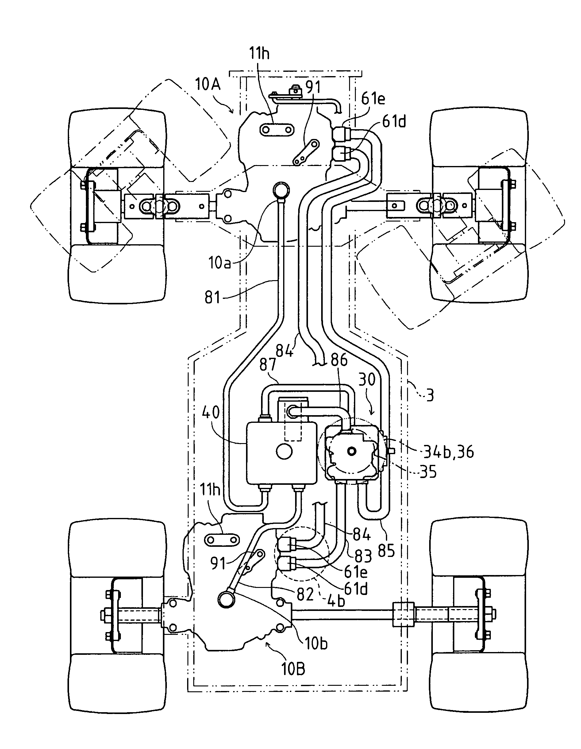
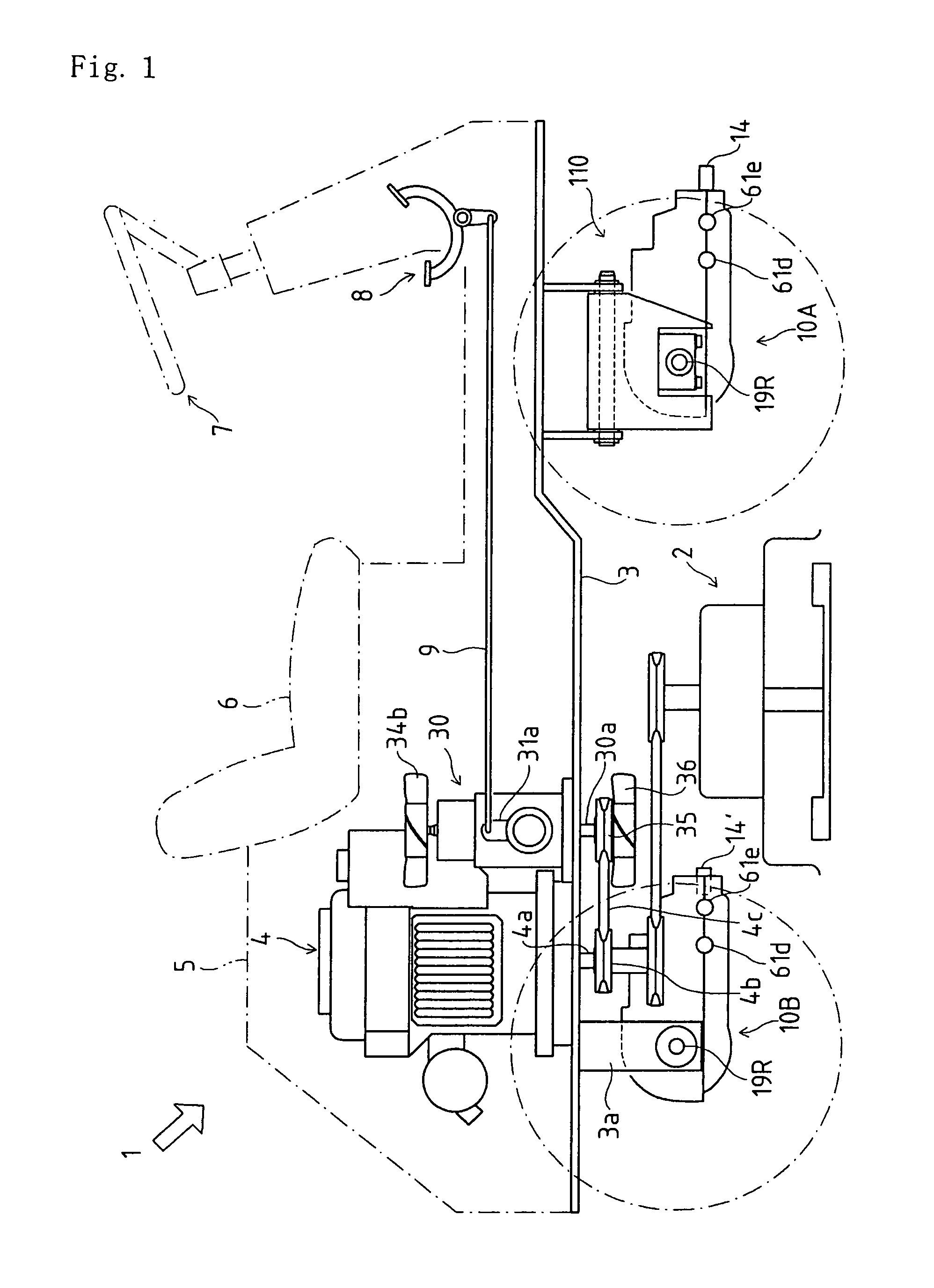
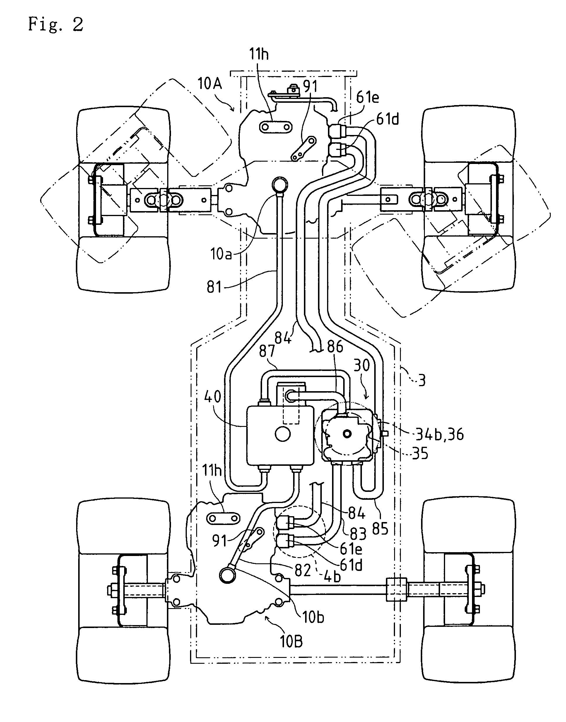
[0044]Referring to a working vehicle 1 shown in FIGS. 1 and 2, a front transaxle 10A, a rear transaxle 10B, and a mower 2 between transaxles 10A and 10B are disposed below a chassis 3. Rear transaxle 10B is laterally eccentrically disposed in vehicle 1 so that left and right axles 19L and 19R projecting laterally outward from rear transaxle 10B are different in length from each other. Left and right brackets 3a holding respective bearings are hung down from chassis 3 so as to journal respective axles 19L and 19R through the respective bearings adjacent to rear tires on outer ends of axles 19L and 19R. Front transaxle 10A is suspended from chassis 3 as discussed later. An engine 4, and a pump unit 30 incorporating a hydraulic pump 33 driven by engine 4 are mounted on chassis 3. Engine 4 and pump unit 30 are enclosed in a bonnet 5 on which a driver's seat 6 is mounted.

[0045]A ...


PUM


Abstract

A hydraulic transaxle including: a variable displacement hydraulic motor with a movable swash plate whose tilt angle defines a displacement of the hydraulic motor; a casing incorporating the hydraulic motor; and a mechanism for determining a range of the tilt angle of the swash plate, wherein the mechanism can fix the tilt angle of the swash plate so as to set the hydraulic motor in a fixed displacement type. A vehicle includes the transaxles for driving respective axles wherein each of the transaxles can select whether the displacement of its hydraulic motor is variable or fixed.

Description

BACKGROUND OF THE INVENTION[0001]1. Field of the Invention[0002]The invention relates to a hydraulic transaxle incorporating a hydraulic motor, and to a vehicle having front and rear hydraulic transaxles having respective hydraulic motors.[0003]2. Related Art[0004]Conventionally, there is a well-known working vehicle having front and rear transaxles incorporating respective hydraulic motors, which are supplied with hydraulic fluid from a pump unit separated from the transaxles, as disclosed in U.S. Pat. No. 6,732,828.[0005]Each of the hydraulic motors is set into either a variable displacement type or a fixed displacement type, corresponding to a steering style of the vehicle comprising the transaxles, such as an Ackerman type or an articulate type.[0006]If a vehicle has the Ackerman type steering mechanism, i.e., has steerable wheels and unsteerable wheels, the steerable wheels must be rotated faster than the unsteerable wheels during turning of the vehicle. If a vehicle has the ar...

Claims


Application Information

Patent Timeline
IPC IPC(8): B60K17/00B60K17/356
CPCB60K17/105B60K17/356
Inventor TSUKAMOTO, MICHIOOKADA, HIDEAKI
Owner KANZAKI KOKYUKOKI MFG
Why Eureka
Try Eureka