L-band optical fiber amplifier with pumping balance

a technology of optical fiber amplifier and balance, which is applied in the field of optical communication, can solve the problems of low conversion efficiency, high manufacturing cost of l-band optical fiber amplifier, and high noise, and achieve the effect of improving the conversion efficiency of pumping and reducing the noise figure and the noise in the optical path, and reducing the manufacturing cos

Active Publication Date: 2022-02-08
ACCELINK TECHNOLOGIES CO LTD
View PDF6 Cites 0 Cited by
  • Summary
  • Abstract
  • Description
  • Claims
  • Application Information

AI Technical Summary

Benefits of technology

[0029]According to the present invention, the backward pumping is applied into the L-band amplifier, and bidirectional pumping is carried out in the first and last erbium-doped fibers that have the largest influence on the noise figure and the conversion efficiency in the optical path. In addition to the erbium-doped optical fibers that are pumped, a relatively short erbium-doped optical fiber that has no pumping injection is added to absorb the ASE. Thus, the problem that the L-band optical fiber amplifier has a high noise when utilizing backward pumping is solved, the pumping conversion efficiency is greatly improved, and the nonlinear four-wave mixing effect is reduced. Meanwhile, the noise figure of the amplifier is effectively reduced, and the manufacturing cost of the L-band optical fiber amplifier is also greatly reduced.

Problems solved by technology

As the L-band optical fiber amplifier includes a large length of erbium-doped optical fibers, when the conventional C-band optical path structure is directly applied in the L-band amplifier, it may cause problems such as a high noise figure, a low conversion efficiency, and series non-linear four-wave mixing in the optical fibers, and the manufacturing cost of the L-band optical fiber amplifier is high.

Method used


Image

  • L-band optical fiber amplifier with pumping balance
  • L-band optical fiber amplifier with pumping balance
  • L-band optical fiber amplifier with pumping balance

Examples


embodiment 1

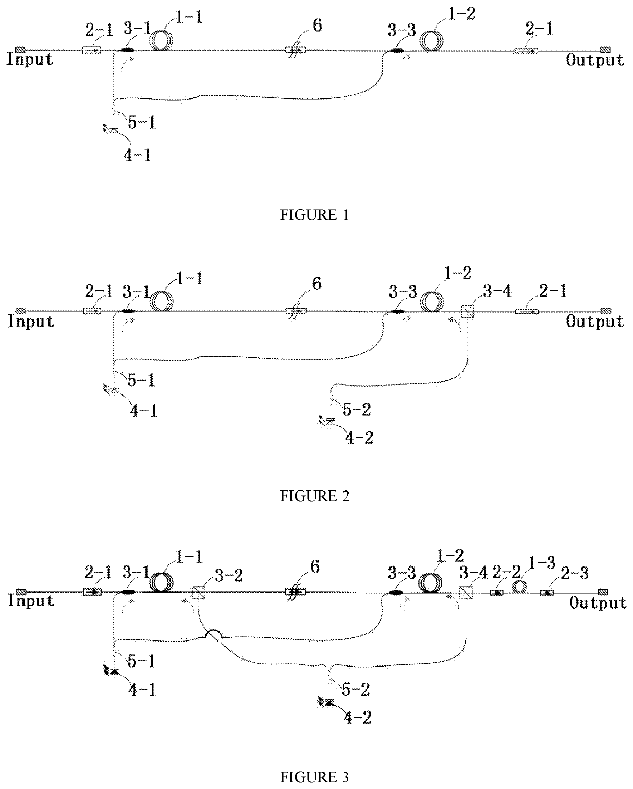
[0043]The embodiment of the present invention provides a balanced pumping L-band optical fiber amplifier, as shown in FIGS. 3-5, comprising a first erbium-doped optical fiber 1-1, a second erbium-doped optical fiber 1-2, an absorbing erbium-doped optical fiber 1-3 and at least two pumping lasers, the first erbium-doped optical fiber 1-1, the second erbium-doped optical fiber 1-2 and the absorbing erbium-doped optical fiber 1-3 being sequentially arranged in this order, the at least two pumping lasers providing pumping light; wherein the first erbium-doped optical fiber 1-1 is injected with forward pumping light and backward pumping light by the at least two pumping lasers, the second erbium-doped optical fiber 1-2 is also injected with forward pumping light and backward pumping light by the at least two pumping lasers. Compared with the existing double forward pumping, the present invention additionally provides backward pumping, so that the two erbium-doped optical fibers both are ...

embodiment 2

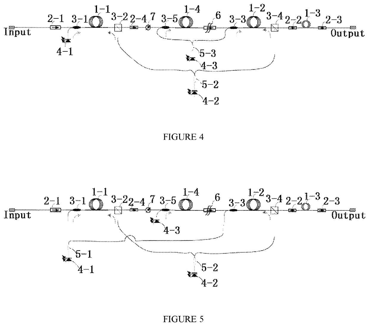
[0053]The specific structure of the fixed gain L-band amplifier FGA has been introduced in Embodiment 1, and on the basis of Embodiment 1, the specific structure of the variable gain L-band amplifier VGA will be introduced in this embodiment. The main difference from the FGA is that a variable optical attenuator (VOA) is added in the VGA. As the variable optical attenuator has a large insert loss, and the gain flatten filter has also a large loss at certain wavelength, the two elements will greatly influence the noise figure if they are placed together. Therefore, the two elements need to be arranged with different erbium-doped optical fibers. For this reason, the VGA structure will have one more erbium-doped optical fiber than the FGA structure, and the one more erbium-doped optical fiber is noted as a third erbium-doped optical fiber 1-4. The third erbium-doped optical fiber 1-4 has little influence on the noise figure and the output power, so it may have bidirectional pumping inj...

embodiment 3

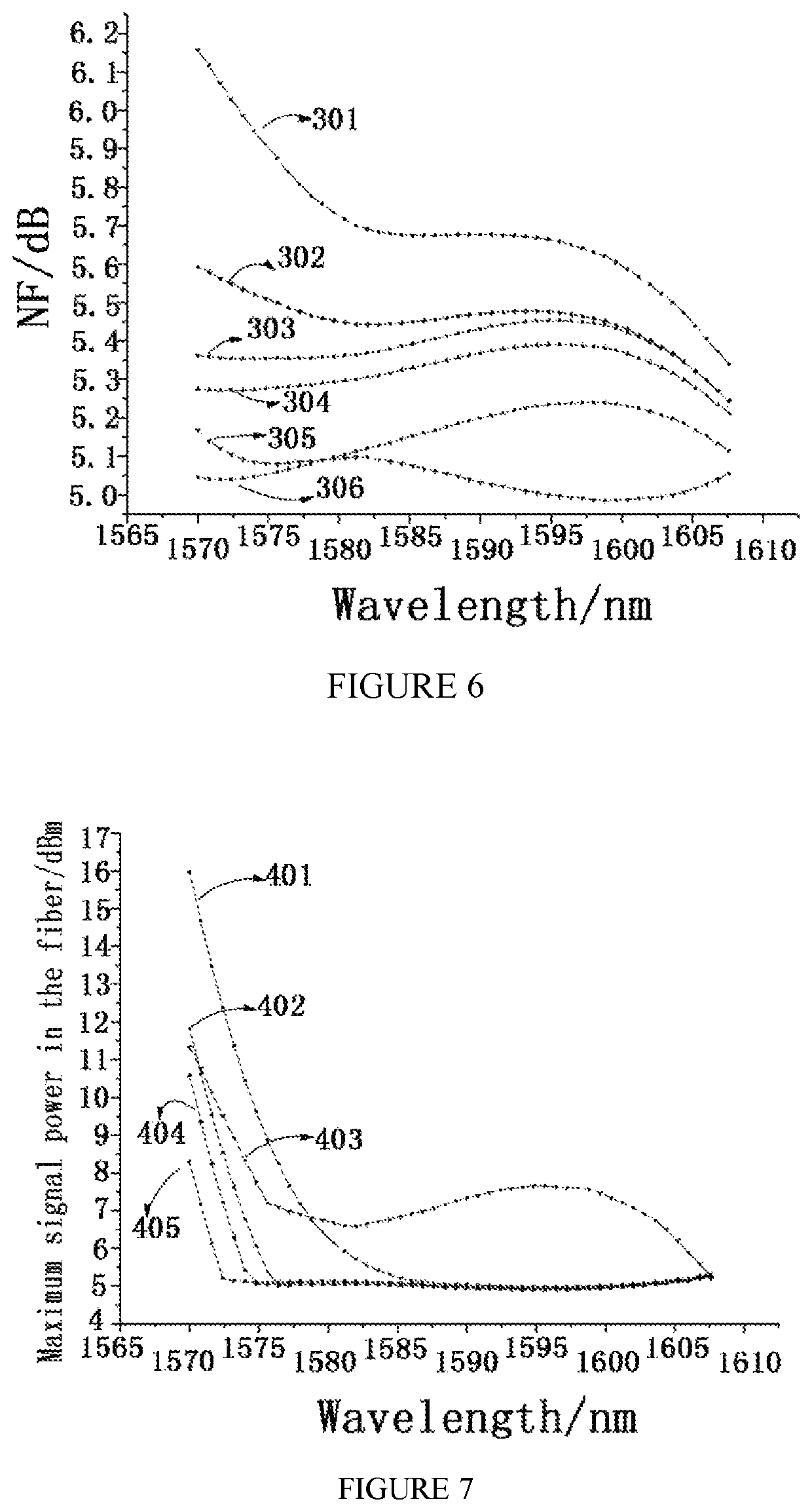
[0062]In the present embodiment, the respective pumping modes are compared by experiments to demonstrate the overall performance of the optical fiber amplifiers provided by the present application. Specifically, taking the FGA provided in the Embodiment 1 as an example, the optical path comprises two erbium-doped optical fibers that need to be injected with pumping light. Under the same gain and output power, a relationship between the noise figure and the pumping modes and a relationship between the non-linear four-wave mixing effect and the pumping modes are studied. The study shows that the overall performance of the optical fiber amplifier is optimal when the two erbium-doped optical fibers both adopt bidirectional pumping and the absorbing erbium-doped fiber is additionally provided. The detailed experiment results are as follows:

[0063]FIG. 6 is a graph showing noise figure curves corresponding to different pumping modes with the same FGA gain and output power. With reference t...


PUM

PropertyMeasurementUnit
wavelengthaaaaaaaaaa

Abstract

The present invention relates to the field of optical communication, and particularly to a balanced pumping L-band optical fiber amplifier comprising a first erbium-doped optical fiber, a second erbium-doped optical fiber, an absorbing erbium-doped optical fiber and at least two pumping lasers, the first erbium-doped optical fiber, the second erbium-doped optical fiber and the absorbing erbium-doped optical fiber being sequentially arranged in this order, and the at least two pumping lasers providing pumping light; wherein the first erbium-doped optical fiber and the second erbium-doped optical fiber both are injected with forward pumping light and backward pumping light, and the absorbing erbium-doped fiber is arranged downstream of the second erbium-doped optical fiber to absorb amplified spontaneous emission (ASE) generated in the amplifier. In the present invention, bidirectional pumping 1s applied in the first and last erbium-doped fibers in the optical path, and an erbium-doped optical fiber that has no pumping injection is added to absorb the ASE. Thus, the pumping conversion efficiency is greatly improved, the nonlinear four-wave mixing effect is reduced, and the problem that the L-band optical fiber amplifier has a high noise when utilizing the backward pumping 1s solved. Meanwhile, the noise figure and the manufacturing cost of the amplifier are reduced.

Description

FIELD OF THE INVENTION[0001]The present invention relates to the field of optical communication, and particularly to a balanced pumping L-band optical fiber amplifier.BACKGROUND OF THE INVENTION[0002]Along with the introduction of the “internet+” concept, the development of technologies such as 5G, cloud computing, big data, and internet of things (IoT) imposes higher demand on bandwidth and rate of the existing communication network. For either a data center or a conventional telecommunication network, a 100 Gbit / s system is widely used, and 200 Gbits / s and 400 Gbit / s systems are in a trial stage. The over-100G system usually uses a dual-carrier or multi-carrier scheme with a modulation format of 8QAM or 16QAM, which has a low spectrum utilization. The conventional C-band (1528-1568 nm) cannot meet the demand for bandwidth, and the demand of the system for L-band (1570-1610 nm) becomes more and more urgent.[0003]An optical fiber amplifier usually includes an optical path structure ...

Claims


Application Information

Patent Timeline
Patent Type & Authority Patents(United States)
IPC IPC(8): H01S3/00H01S3/067H01S3/094H01S3/16
CPCH01S3/06787H01S3/0677H01S3/06758H01S3/094011H01S3/1608H01S2301/02H01S3/06716H01S3/06754H01S3/094003H01S3/094096H01S2301/03H01S2301/04H01S3/094061
Inventor FU, CHENGPENGYU, ZHENYULIU, QINGLE, MENGHUIYU, CHUNPING
Owner ACCELINK TECHNOLOGIES CO LTD
Why Eureka
Try Eureka