Image sensing system and method
- Summary
- Abstract
- Description
- Claims
- Application Information
AI Technical Summary
Benefits of technology
Problems solved by technology
Method used
Image
Examples
Embodiment Construction
)
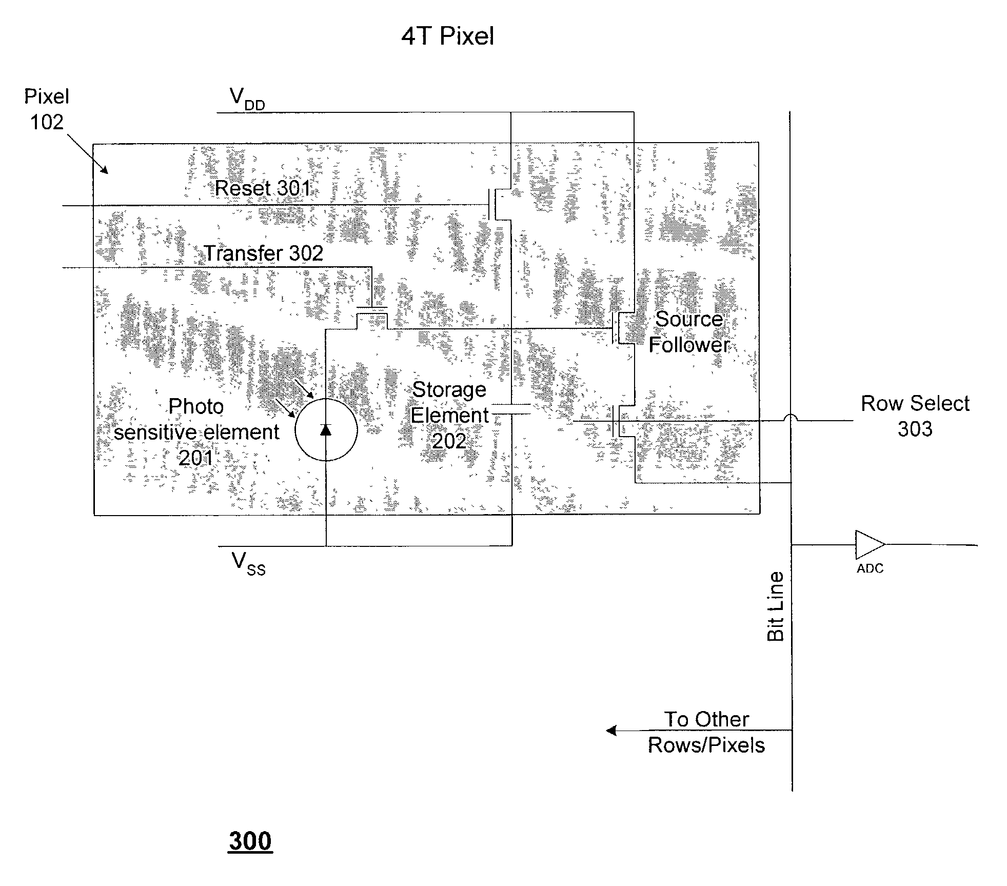
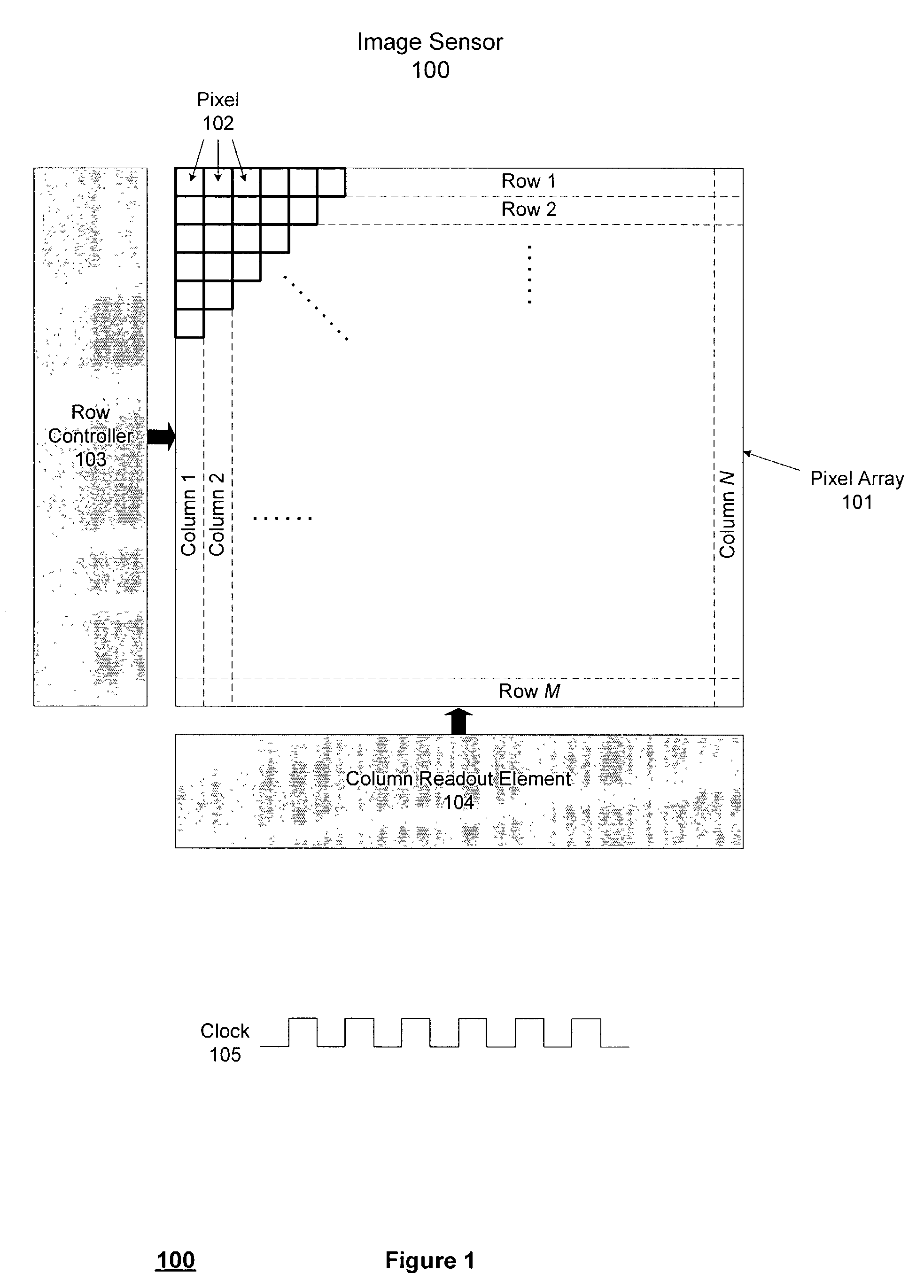
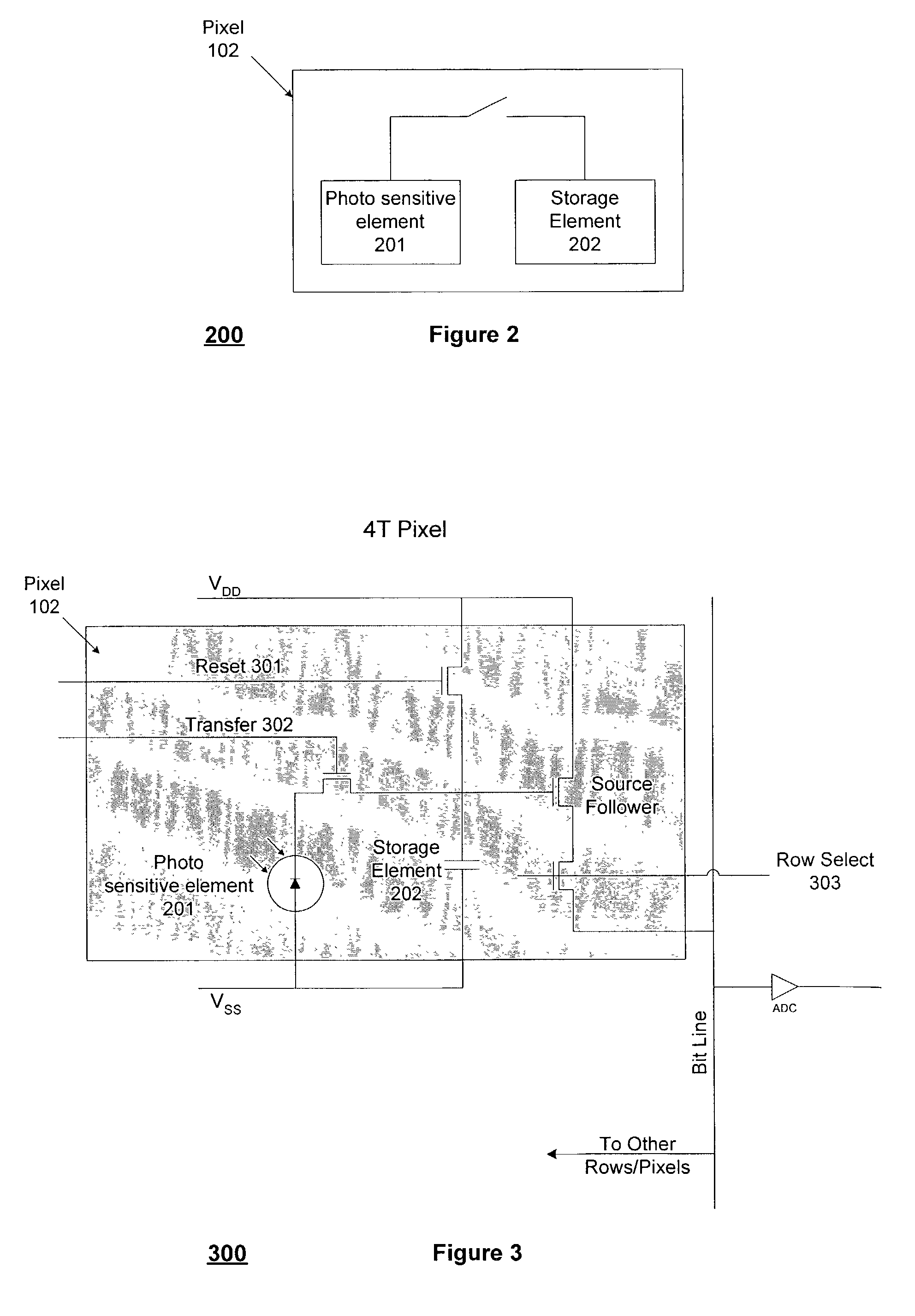
[0012]FIG. 1 shows an image sensor 100 in accordance with a preferred embodiment of the present invention. An array 101 of pixels 102 is arranged in M rows and N columns, such as M=1024 rows by N=1280 columns, or any other dimensions depending on application. Row controller 103 couples to pixel array 101 and supplies control signals to pixel array 101. Column readout element 104 couples to pixel array 101 and performs readouts from pixel array 101. The timing of the present invention proceeds according to a clock 105, such as one operating at 48 MHz or some other frequency depending on application. As shown in FIG. 2, pixel 102 has a photo sensitive element 201, such as a photodiode or a photogate or a PIN diode, as well as an internal storage element 202, such as a capacitor. Preferably, pixel 102 is a 4T pixel with a photo sensitive element 201, a storage element 202, a Reset control line 301, a Transfer control line 302, and a Row Select control line 303, as shown in FIG. 3. Hav...
PUM
 Abstract
Description
Claims
Application Information
 - R&D
- Intellectual Property
- Life Sciences
- Materials
- Tech Scout
- Unparalleled Data Quality
- Higher Quality Content
- 60% Fewer Hallucinations
Browse by: Latest US Patents, China's latest patents, Technical Efficacy Thesaurus, Application Domain, Technology Topic, Popular Technical Reports.
© 2025 PatSnap. All rights reserved.Legal|Privacy policy|Modern Slavery Act Transparency Statement|Sitemap|About US| Contact US: help@patsnap.com


