Sheet transport device

a technology of transport device and sheet metal, which is applied in the direction of thin material handling, electrical equipment, pictoral communication, etc., can solve the problems of contamination entering the internal portion of the device, the discharge tray is damaged, and the discharge tray is removed

Inactive Publication Date: 2008-06-10
BROTHER KOGYO KK
View PDF8 Cites 8 Cited by
  • Summary
  • Abstract
  • Description
  • Claims
  • Application Information

AI Technical Summary

Benefits of technology

[0012]Another object of this invention is to prevent contaminants entering an internal portion of the device through an opening formed on a housing of the device from falling on a control substrate.
[0018](2) Each of the shafts may preferably be reduced in diameter to its front end in a tapered fashion. When the load is applied on the main tray of the discharge tray in the retention posture, the load is transmitted to the shafts of the device main body via the bearings. Since each of the shafts is reduced in diameter to the front end in tapered fashion, the bearing moves toward the front end in such a manner as to slide down the shaft. Thus, the bearings move readily toward the front ends of the shafts in accordance with the load applied on the main tray.
[0023](7) The discharge tray may preferably cover an operation panel provided on the device main body in the bending posture. With the operation panel covered with the discharge tray, inadvertent input to the operation panel is prevented when the device is not used.
[0025](9) The window of the discharge tray may be provided with a transparent member. Due to the transparent member, contents displayed on the liquid crystal display unit are confirmed when the discharge tray is in the bending posture. Further, unwanted contact onto the liquid crystal display unit is prevented.
[0026](10) The discharge tray may be provided with an extension tray capable of moving in and out of the main tray. The extension tray changes its posture between an extension posture for projecting from an end of the main tray and a housing posture for being housed in the main tray. When the extension tray is in the extension posture, an area for retaining the sheet on the extension tray is added to the area for retaining the sheet by a main tray. Due to the extension tray, the discharge tray retains a sheet having a larger size. When the extension tray is in the housing posture, a size of the discharge tray is reduced.
[0027](11) As described in the foregoing, according to this invention, the bearings move a distance longer than a length of the shafts to cause the discharge tray to come off the device main body when the load of sheet, the load of impact, or the like larger than the predetermined degree is applied on the discharge tray in the retention posture. Because the discharge tray thus comes of f the device main body, the bearings and the shafts are prevented from being damaged when the load larger than a bearable load is applied on the discharge tray. In the bending posture, the locking members lock the bearings to restrain the bearings to move in the shaft direction. Because the bearings are thus restrained, the discharge tray is prevented from coming off the device main body.

Problems solved by technology

However, when the discharge tray is closed, it is unlikely that the discharge tray will be damaged.
It is undesirable that the discharge tray comes off when the discharge tray is closed.
Contaminants may enter the internal portion of the device through the opening.
Particularly, if the contaminants are fallen on a control substrate, an electrical failure can be caused by the contaminants.
In view of assembly of the wirings and the like, it is undesirable to cover the control substrate with a cover before finishing the wirings.

Method used


Image

  • Sheet transport device
  • Sheet transport device
  • Sheet transport device

Examples


Embodiment Construction

[0042]Hereinafter, this invention will be described in detail with reference to the drawings and based on preferred embodiments.

(Overall Structure)

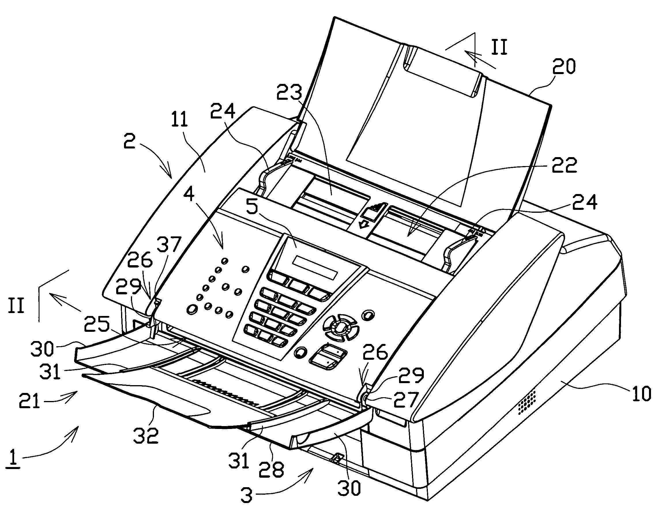
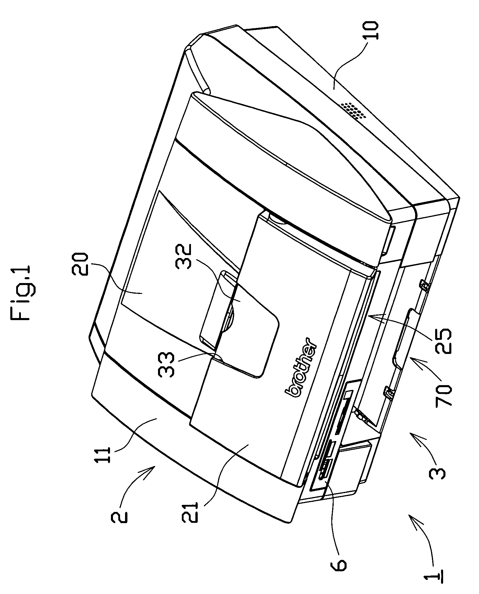
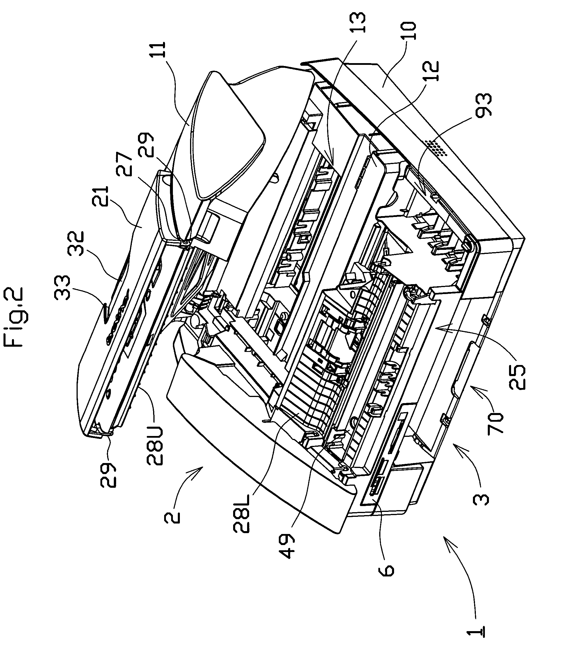
[0043]FIG. 1 is a diagram showing an appearance of a multifunction device 1 according to one embodiment of this invention. The multifunction device 1 have a scanner function, a printer function, and a facsimile function in an integral fashion. The multifunction device 1 can be divided roughly into 2 units according to the functions which are an upper unit and a lower unit. The upper unit of the multifunction device 1 is a scanner unit 2 for reading an image of a document. The lower unit of the multifunction device 1 is a printer unit 3 for recording the image on a recording paper. The sheet transport device according to this invention is mounted on the scanner unit 2 of the multifunction device 1. A structure of the multifunction device 1 to be described in detail below is one example of the sheet transport device according to this invent...


PUM


Abstract

A sheet transport device according to this invention is provided with: a sheet tray on which a sheet to be transported is placed; a device main body provided with a transport path led from the sheet tray to a discharge outlet; a transport mechanism for transporting the sheet from the sheet tray to the discharge outlet via the transport path; shafts projecting from positions in the vicinity of opposite ends of the discharge outlet of the device main body to horizontal directions opposite to each other; a discharge tray having a main tray which retains the discharged sheet and is provided with bearings for the shafts; and locking members provided in the vicinity of the shafts of the device main body. The locking members lock the shafts of the discharge tray in the bending posture. This locking prevents the discharge tray in the bending posture from coming off the device main body. The locking members allow the bearings of the discharge tray in the bending posture to move toward the front ends of the shafts. The bearings come off the shafts when a load larger than a predetermined one is applied on the main tray.

Description

BACKGROUND OF THE INVENTION[0001]1. Field of the Invention[0002]The present invention relates to a sheet transport device transporting a sheet via a predetermined transport path. This invention is applicable particularly to an image reading apparatus such as a facsimile and photocopier; however, its application is not limited to the above cases, and the invention is useful for other types of apparatuses.[0003]2. Description of the Related Art[0004]The sheet transport device transports a sheet from a sheet tray to a discharge tray via a transport path. The discharge tray is attached to a main body of the sheet transport device with a hinge member for the purpose of downsizing the device. The discharge tray is bent toward the device main body when the sheet transport device is not in use and is so opened as to retain the sheet when using the sheet transport device.[0005]A sheet tray wherein an auxiliary tray is coupled rotatably thereto with a hinge member which is formed of a project...

Claims


Application Information

Patent Timeline
Patent Type & Authority Patents(United States)
IPC IPC(8): B65H31/00
CPCB65H31/02B65H2402/31B65H2402/46B65H2402/515B65H2405/324B65H2801/06B65H2402/51
Inventor MURAI, SHUNJI
Owner BROTHER KOGYO KK
Why Eureka
Try Eureka