
Manganese activated zinc silicate phosphor and plasma display panel

a technology of activated zinc silicate phosphor and plasma display panel, which is applied in the direction of luminescent compositions, gas-filled discharge tubes, chemistry apparatus and processes, etc., can solve the problems of flicker of images, lowering emission intensity, and not fully satisfying with emission intensity, so as to reduce afterglow time and high white luminance intensity , the effect of high emission intensity

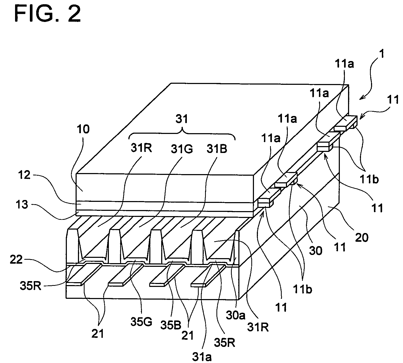
Inactive Publication Date: 2008-06-10
KONICA MINOLTA INC
View PDF2 Cites 0 Cited by
  • Summary
  • Abstract
  • Description
  • Claims
  • Application Information

AI Technical Summary

Benefits of technology

[0012]An object of the present invention is to provide a manganese activated zinc silicate phosphor which exhibits high emission intensity and reduced afterglow time and a PDP utilizing the same which exhibits a high white luminance intensity and a high luminance maintaining ratio.

Problems solved by technology

On the other hand, successive display of information within a very short time unit is required for providing smooth moving image of a display, however, Zn2SiO4:Mn (green) has a rather long afterglow, resulting in a problem of causing an after-image and a flicker of an image when the display moves to a next image.
However, emission intensity and afterglow time are in a trade-off relationship in many cases and there has been a problem of lowering emission intensity when afterglow time is shortened by increasing an amount of a manganese activator.
However, it is not fully satisfactory with respect to emission intensity and a reduction effect of afterglow time even when quantity of activator is controlled and particle size distribution is improvement in the above technique, and further improvement is still required.
Further, a phosphor layer of each color utilized in a PDP is deteriorated by ultraviolet ray irradiation and ion bombardment at discharging, resulting in reduction of luminance with increasing lighting time of the PDP.
Particularly, with respect to ion bombardment, employed in many PDPs are a method in which a phosphor is provided on the other substrate so as to oppose to a pair of display electrodes via a discharge space and are excited to emit light by ultraviolet rays generated by plane discharge between the display electrodes, to avoid ion bombardment at the discharge, however, these are still not fully satisfactory and improvement of a life time characteristic has been an important problem to improve characteristics of a PDP.

Method used


Image

  • Manganese activated zinc silicate phosphor and plasma display panel
  • Manganese activated zinc silicate phosphor and plasma display panel
  • Manganese activated zinc silicate phosphor and plasma display panel

Examples


example 1

: Green Phosphor

[0102]Each of manganese activated zinc silicate phosphors 1-1 through 1-10 was prepared in the following manner.

(Preparation of Manganese Activated Zinc Silicate Phosphor 1-1)

[0103]755 g of colloidal silica (PL-3, manufactured by Fuso Chemical Co., Ltd.) and 735 g of ammonia water (28%) were mixed with pure water and the volume was adjusted to 5000 ml to prepare Solution A. Simultaneously, 1613 g of zinc nitrate hexahydrate (manufactured by KANTO KAGAKU, purity of 99.0%), 180 g of manganese nitrate hexahydrate (manufactured by KANTO KAGAKU, purity of 98.0%) and 0.55 g of barium nitrate (manufactured by KANTO KAGAKU, purity of 99.0%) were mixed with pure water and the volume was adjusted to 5000 ml to prepare Solution B.

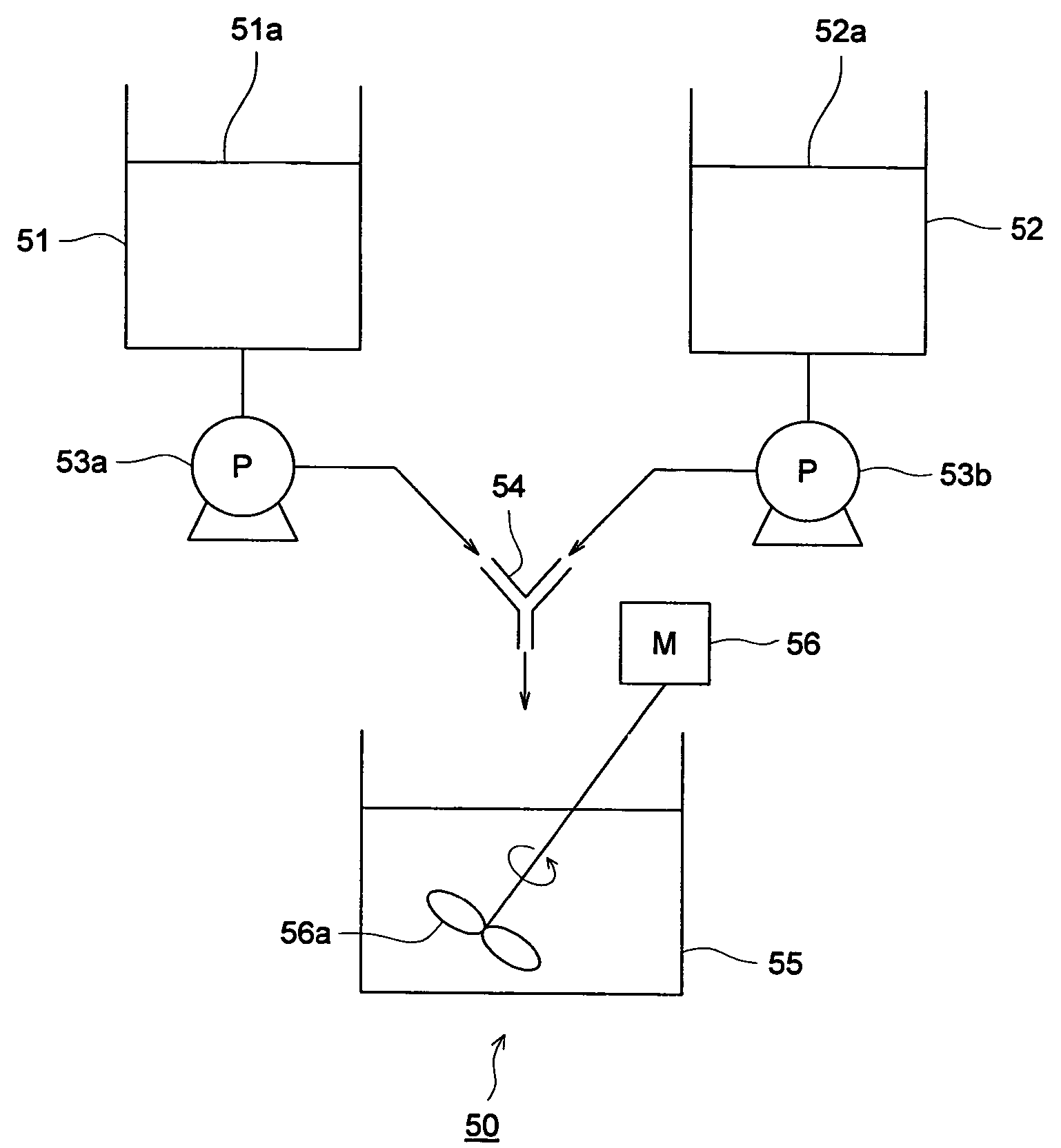
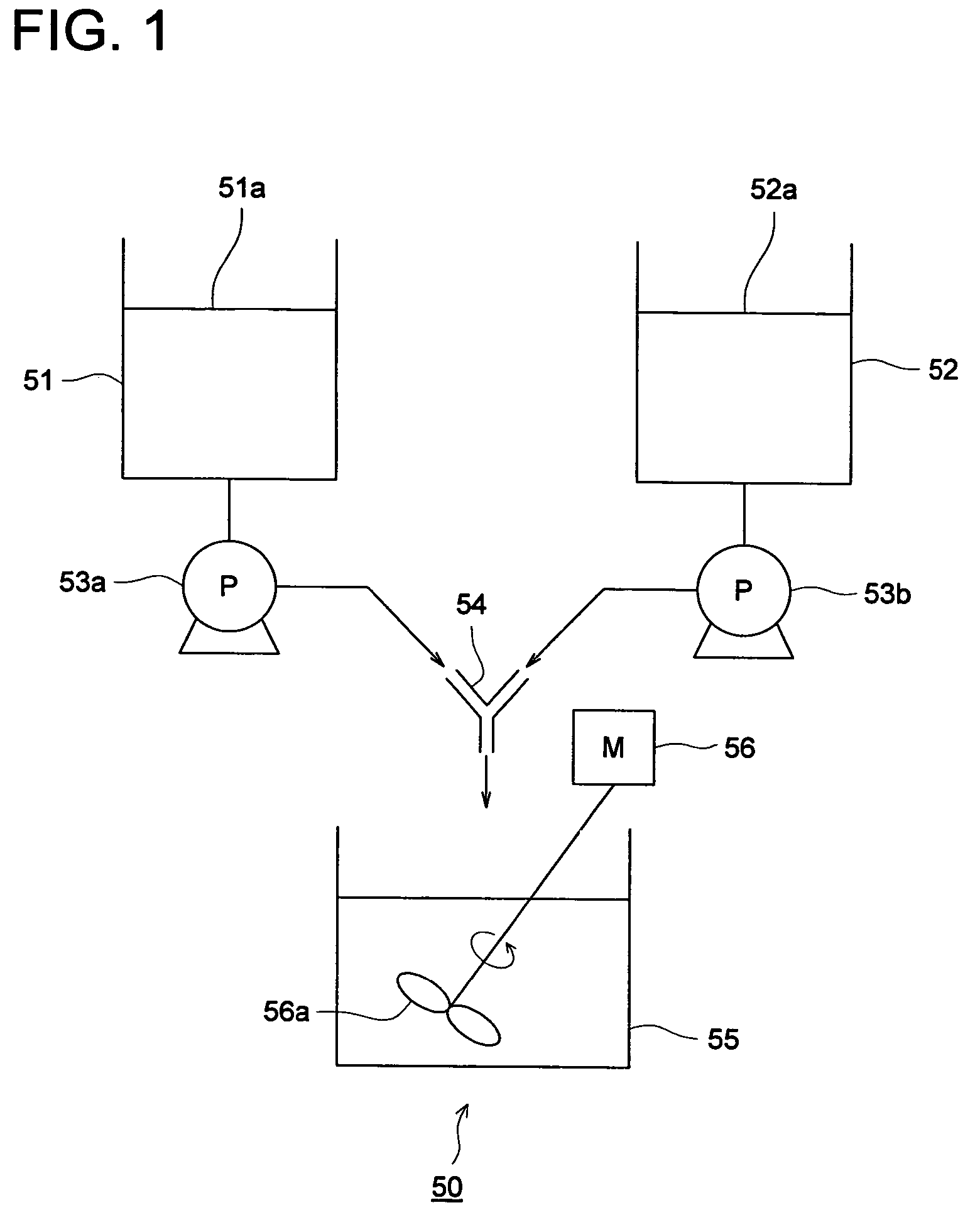
[0104]Solution A and Solution B, after kept at 40° C., were supplied to the Y-shaped reaction apparatus shown in FIG. 1 at an addition rate of 1800 ml / min by use of a roller pump. The precipitate obtained was diluted with pure water and filtered by pre...

example 2

[0122]PDPs 2-1 through 2-10 were assembled by using phosphor layers containing phosphors of manganese activated zinc silicate phosphors 1-1-1-10 prepared as in example 1, a blue emission phosphor and a red emission phosphor both of which were prepared according to the method described below. White luminances of the assembled PDPs were evaluated.

(1) Preparation of a Red Emission Phosphor [(Y,Gd)BO3:Eu3+]

[0123]A red emission phosphor precursor was formed by a reaction crystallization method in the presence of a protective colloid. First, gelatin (having a mean molecular weight of approximately 15,000) was dissolved in 300 ml of pure water so as to make the concentration of 5 weight % to prepare Solution A.

[0124]Further, 28.99 g of yttrium nitrate hexahydrate, 15.88 g of gadolinium nitrate and 2.60 g of europium nitrate hexahydrate were dissolved in pure water so as to prepare a solution of 150 ml resulting in preparation of Solution B. Further, 8.20 g of boric acid were dissolved in p...


PUM

PropertyMeasurementUnit
molar ratioaaaaaaaaaa
particle diameteraaaaaaaaaa

Abstract

A manganese activated zinc silicate phosphor comprising phosphor particles having a crystal lattice distortion factor of 0.01 to 1.0% which exhibits high emission intensity and reduced afterglow time and a PDP utilizing the same which exhibits high white luminance and a high luminance maintaining ratio.

Description

[0001]This application is based on Japanese Patent Application No. 2004-164400 filed on Jun. 2, 2004, in Japanese Patent Office, the entire content of which is hereby incorporated by reference.FIELD OF THE INVENTION[0002]The present invention relates to a manganese activated zinc silicate phosphor and a plasma display panel utilizing the same.BACKGROUND OF THE INVENTION[0003]A plasma display panel (hereinafter, referred to as a PDP) is provided with two sheets of glass substrates equipped with electrodes and phosphor layers in a plurality of cells which are separated by walls formed between the substrates. When a cell is discharged by applying voltage between electrodes, UV (ultraviolet) rays are generated, which are attributed to a discharge gas sealed in a cell, and the UV rays activate phosphor resulting in emission of visible light. At present, phosphors predominantly utilized for a PDP application include, for example, (Y, Gd) BO3:Eu (red), Zn2SiO4:Mn (green), BaMgAl10O17:Eu (b...

Claims


Application Information

Patent Timeline
Patent Type & Authority Patents(United States)
IPC IPC(8): C09K11/54C09K11/59C09K11/06C09K11/77H01J11/12H01J11/42
CPCC09K11/595C09K11/7734C09K11/7797H01J11/42H01J11/12
Inventor HOSHINO, HIDEKIFURUSAWA, NAOKOOKADA, HISATAKE
Owner KONICA MINOLTA INC
Learn More