Phosphor, Manufacture Thereof; Light-Emitting Device, and Image Display Device Utilizing Phosphor

a technology of phosphor and phosphor, which is applied in the field of phosphor, can solve the problems of difficulty in artificial crystal structure construction, and achieve the effects of low temperature fluctuation, high emission efficiency, and high brightness

Active Publication Date: 2013-08-15
NAT INST FOR MATERIALS SCI
View PDF8 Cites 17 Cited by
  • Summary
  • Abstract
  • Description
  • Claims
  • Application Information

AI Technical Summary

Benefits of technology

[0035]In accordance with the present invention, it is possible to utilizes, as a phosphor, an inorganic compound satisfying the above composition, which can be obtained by firing a raw material mixture made to be a specific composition in a predetermined condition. It can also be a blue phosphor with high brightness if the composition is well controlled. Further, a white color light-emitting diode (light-emitting unit) having high emission efficiency and little temperature fluctuation can be obtained by utilizing the phosphor, and an illuminating device with the diode and an image display device of bright coloration can also be obtained. Since the brightness of the phosphor does not decrease even when exposed to the excitation source, the present invention provides a useful phosphor suitably used for the light-emitting unit such as the white light-emitting diode, the illuminating device, a backlight source for a liquid crystal, VFD, FED, PDP or CRT. Further, the phosphor absorbs ultraviolet light, and thus the phosphor is suitable for a pigment and ultraviolet absorber.

Problems solved by technology

However, it is quite difficult to construct a crystal structure artificially as if it were to put building blocks together.

Method used


Image

  • Phosphor, Manufacture Thereof; Light-Emitting Device, and Image Display Device Utilizing Phosphor
  • Phosphor, Manufacture Thereof; Light-Emitting Device, and Image Display Device Utilizing Phosphor
  • Phosphor, Manufacture Thereof; Light-Emitting Device, and Image Display Device Utilizing Phosphor

Examples


examples

[0132]The present invention will be described in more detail with reference to the examples to be shown below, but these examples are disclosed only for the purpose of facilitating understanding the present invention readily such that the present invention is not limited to these examples.

[Raw Materials Used for Synthesis]

[0133]The raw material powders used for the synthesis were: silicon nitride powder with a particle size of specific surface area of 11.2 m2 / g, oxygen content of 1.29 wt %, and a type content of 95% (SN-E10 grade made by Ube Industries, Ltd.); silicon dioxide powder (SiO2; made by Kojundo Chemical Laboratory Co., Ltd.); aluminum nitride powder with a particle size of specific surface area of 3.3 m2 / g and oxygen content of 0.82 wt % (E grade made by Tokuyama Corporation); aluminum oxide powder with a particle size of specific surface area of 13.2 m2 / g (TAIMICRON made by Daimei Chemicals Co., Ltd.); calcium oxide (made by Kojundo Chemical Laboratory Co., Ltd.); stront...

examples 67 to 70

[0160]Next, a light-emitting unit utilizing the phosphor of the present invention will be described.

example 67

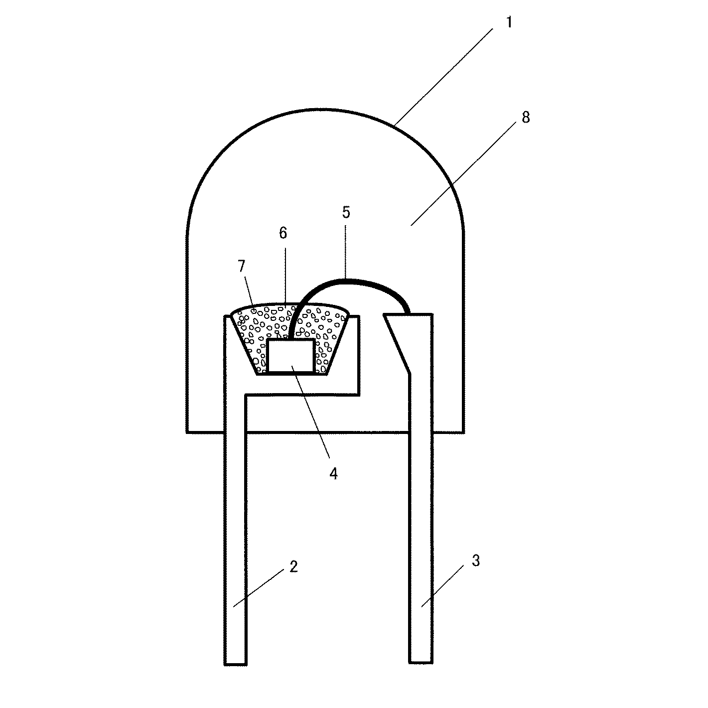
[0161]FIG. 5 is a schematic diagram showing an illuminating device (bullet-type of LED illuminating device) according to the present invention.

[0162]A so-called bullet-type white light-emitting diode lamp (1) as shown in FIG. 5 was produced. There are two lead wires (2, 3), one of which (2) has a recess, in which a blue light-emitting diode element (4) having an emission peak of 365 nm is placed. The lower electrode of the ultraviolet light-emitting diode element (4) and the bottom surface of the recess are electrically connected with conductive paste, and the upper electrode and the other lead wire (3) are electrically connected through a gold thin wire (5). The phosphor (7) is dispersed in resin and mounted in the vicinity of the light-emitting diode element (4). The first resin (6) in which this phosphor is dispersed is transparent, and covers the entire ultraviolet light-emitting diode element (4). The tip-top portion of the lead wire including the recess, the blue light-emittin...


PUM

PropertyMeasurementUnit
mass %aaaaaaaaaa
mass %aaaaaaaaaa
mean particle diameteraaaaaaaaaa

Abstract

Provided is a chemically and thermally stable phosphor having different emission characteristics than the conventional phosphor and exhibiting high emission intensity if combined with an LED of 470 nm or less. The phosphor of the present invention is represented by a composition formula: MdAeDfEgXh (d+e+f+g+h=1; M is one or more kinds of elements selected from Mn, Ce, Pr, Nd, Sm, Eu, Tb, Dy, and Yb; A is one or more kinds of elements selected from Mg, Ca, Sr, and Ba; D is one or more kinds of elements selected from Si, Ge, Sn, Ti, Zr, and Hf; E is one or more kinds of elements selected from B, Al, Ga, In, Sc, Y, and La; and X is one or more kinds of elements selected from O, N, and F) and parameters d, e, f, g, and h satisfy the predetermined condition.

Description

CROSS-REFERENCE TO RELATED APPLICATION[0001]This application is a continuation of International Application No. PCT / JP2012 / 78870, filed on Nov. 7, 2012, the entire contents of which are incorporated herein by reference. This application also claims the benefit of priority from Japanese Patent Application No. 2011-243556 filed on Nov. 7, 2011, the entire contents of which are incorporated herein by reference.TECHNICAL FIELD[0002]The present invention relates to a phosphor expressed by a compositional formula of MdAeDfEgXh (where d+e+f+g+h=1; an M element is one or two or more kinds of elements selected from the group consisting of Mn, Ce, Pr, Nd, Sm, Eu, Tb, Dy, and Yb; an A element is one or two or more kinds of elements selected from the group consisting of Mg, Ca, Sr, and Ba; a D element is one or two or more kinds of elements selected from the group consisting of Si, Ge, Sn, Ti, Zr, and Hf; an E element is one or two or more kinds of elements selected from the group consisting of...

Claims


Application Information

Patent Timeline
Patent Type & Authority Applications(United States)
IPC IPC(8): C09K11/77H05B33/12
CPCC09K11/0883C09K11/7734H01L2224/8592H01J61/44H05B33/14H01L33/502C09K11/7703H01J1/63C09K11/7786C09K11/7761C09K11/7746C09K11/7731C09K11/7718H05B33/12H01L2224/48091H01L2224/48247H01L2224/73265H01L2924/00014H01L2924/12044H01L2924/181H01L2224/45144C09K11/77348H01L2924/00H01L2924/00012
Inventor HIROSAKI, NAOTOTAKEDA, TAKASHIFUNAHASHI, SHIRO
Owner NAT INST FOR MATERIALS SCI
Why Eureka
Try Eureka