Light emitting device and lighting device using it, image display unit

a technology of light emitting device and image display unit, which is applied in the direction of discharge tube/lamp details, discharge tube luminescent screen, discharge tube/lamp details, etc., can solve the problem of insufficient emission intensity, led or ld is difficult to stably produce the emission wavelength with a high degree of accuracy, and the emission efficiency is significant. the effect of high emission intensity

Inactive Publication Date: 2007-06-14
MITSUBISHI CHEM CORP
View PDF11 Cites 19 Cited by
  • Summary
  • Abstract
  • Description
  • Claims
  • Application Information

AI Technical Summary

Benefits of technology

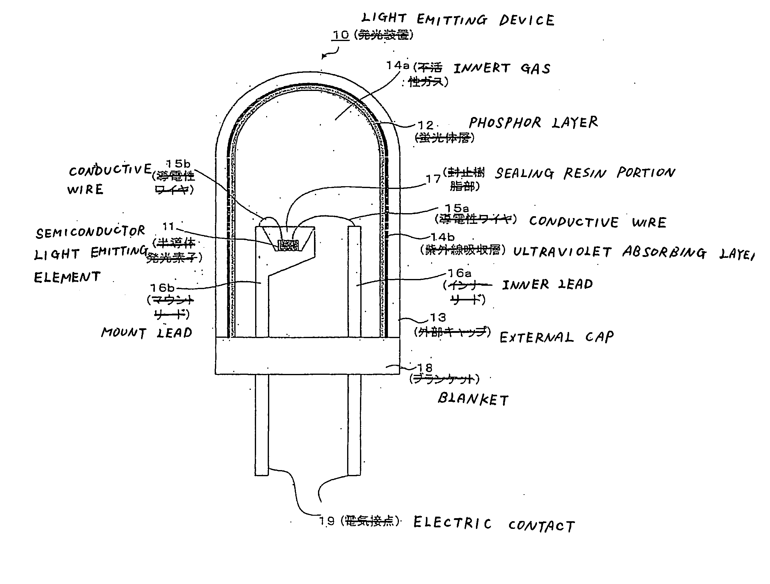
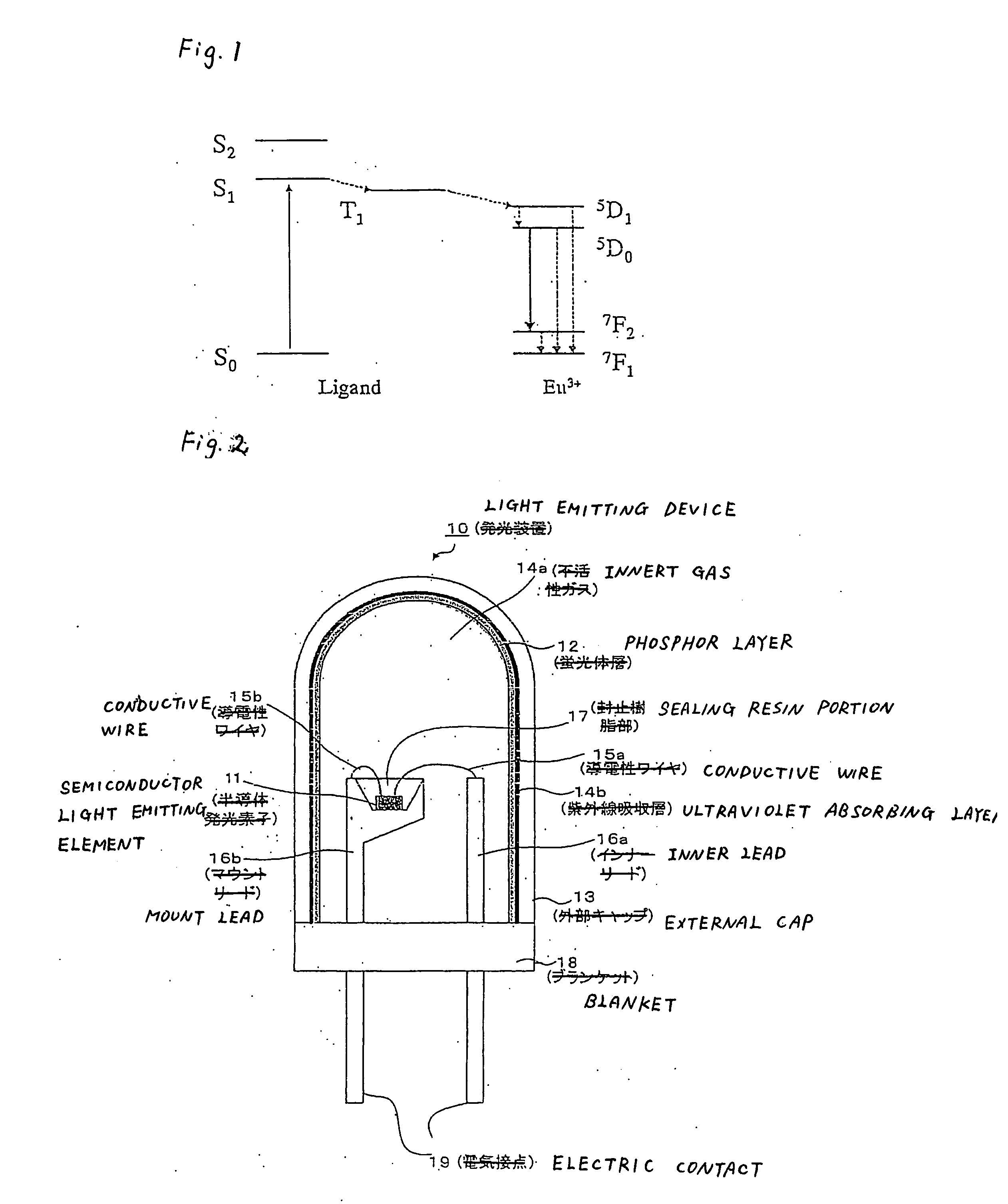
[0026] According to the present invention, there can be provided a light emitting device which is stable and high in emission intensity.

Problems solved by technology

However, the red phosphor such as Y2O2S:Eu mainly used in the light emitting device at present has the problem of a significant decrease in emission efficiency when light in the region from near-ultraviolet light to visible light is used as an excitation source, because absorption at a wavelength of 360 nm or more in the near-ultraviolet region is small.
On the other hand, the LED or LD is difficult to stably produce the emission wavelength with a high degree of accuracy, and in addition, the emission wavelength also shifts by a change in temperature or current to deviate ±5 nm from the center wavelength in some cases.
The emission intensity is therefore insufficient in considering a balance with the blue and green phosphors.

Method used


Image

  • Light emitting device and lighting device using it, image display unit
  • Light emitting device and lighting device using it, image display unit
  • Light emitting device and lighting device using it, image display unit

Examples


example 1

[0086] Synthesis of Eu(TTA)3(TPPO)2

[0087] 0.67 g (3.0 mmol) of 4,4,4-trifluoro-1-(2-thienyl)-1,3-butanedione (H-TTA), 0.56 g (2.0 mmol) of triphenylphosphine oxide (TPPO) and 0.32 g (3.0 mmol) of 2,2′-iminodiethanol were dissolved in 40 ml of isopropanol. To this solution, a solution obtained by dissolving 0.37 g (1 mmol) of europium chloride (III) hexahydrate in 20 ml of a mixed solvent of water / isopropanol (1 / 4) was added dropwise at room temperature taking 2 hours, and stirring was further continued at room temperature for 1 hour. A precipitate formed was filtered by suction, and washed with water and isopropanol. The resulting light yellow powder was dried under vacuum at 50° C. to obtain a desired product Eu(TTA)3(TPPO)2 represented by the following structural formula. The melting point of this complex was from 248° C. to 251° C.

example 2

[0088] Synthesis of Eu(TTA)3Phen

[0089] 6.67 g (30 mmol) of H-TTA, 1.98 g (10 mmol) of 1,10-phenanthroline (Phen) monohydrate and 3.16 g (30 mmol) of 2,2′-iminodiethanol were dissolved in 500 ml of ethanol. To this solution, a solution obtained by dissolving 3.67 g (10 mmol) of europium chloride (III) hexahydrate in 200 ml of ethanol was added dropwise at room temperature taking 4 hours, followed by further standing at room temperature for several hours. Then, a precipitate formed was filtered by suction, and washed with ethanol. The resulting light yellow powder was dried under vacuum at 50° C. to obtain a desired product Eu (TTA)3Phen represented by the following structural formula.

[0090] Elemental analysis of this complex showed 43.33% C, 2.36% H and 2.78% N, which were approximately identical to calculated values, 43.43% C, 2.02% H and 2.81% N. Further, the melting point of this complex was from 242° C. to 243° C.

[0091] For the resulting Eu(TTA)3Phen complex, a powder X-ray di...

example 3

[0095] Synthesis of Eu(TTA)3IQNO

[0096] 0.67 g (3 mmol) of H-TTA, 0.15 g (1 mmol) of isoquinoline-N-oxide (IQNO) and 0.32 g (3 mmol) of 2,2′-iminodiethanol were dissolved in 25 ml of ethanol. To this solution, a solution obtained by dissolving 0.37 g (10 mmol) of europium chloride (III) hexahydrate in 20 ml of ethanol was added dropwise at room temperature, and then, 15 ml of water was added, followed by stirring at room temperature for several hours. A precipitate obtained was filtered by suction, and washed with water. The resulting light yellow powder was dried under vacuum at 50° C. to obtain a desired product Eu(TTA)3IQNO represented by the following structural formula. The melting point of this complex was from 249° C. to 251° C.


PUM

PropertyMeasurementUnit
excitation wavelengthaaaaaaaaaa
peak wavelengthaaaaaaaaaa

Abstract

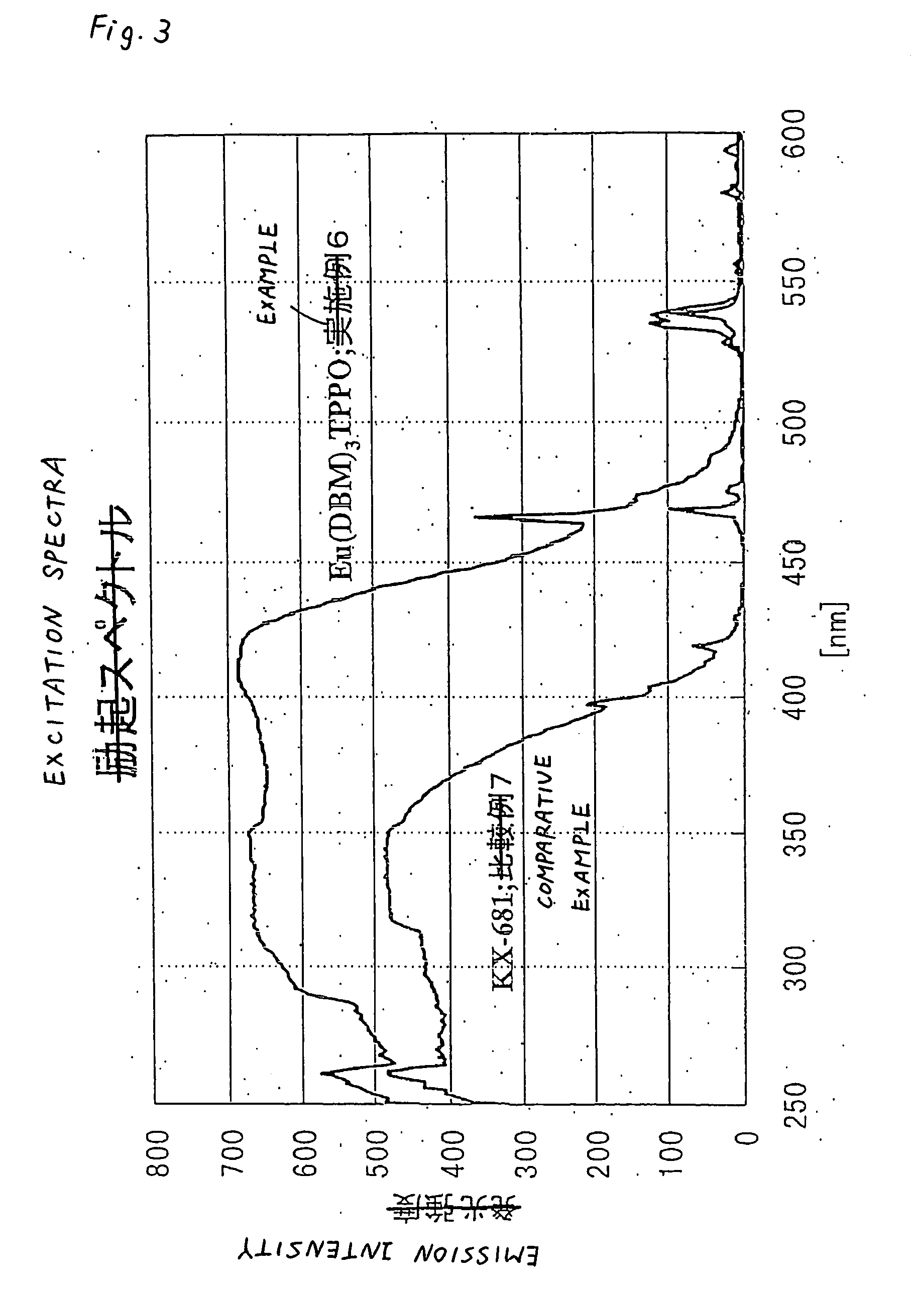
An object of the present invention is to provide a light emitting device which is high in emission intensity and stable, that is to say, a light emitting device in which when an LED or LD having an emission peak at 380 nm to 410 nm is used as an excitation light source of the light emitting device, the emission intensity of a red phosphor does not largely change to some deviation of the emission wavelength of the LED or LD to maintain not only brightness but also a balance at the time when mixed with a blue and green phosphors.
The present invention relates to a light emitting device characterized in that the device comprises a phosphor which has Eu3+ as a luminescent center ion, in which a minimum emission intensity within the excitation wavelength range of 380 nm to 410 nm in an excitation spectrum is 65% or more of a maximum emission intensity, and which has an emission efficiency at 400 nm of 20% or more, and a semiconductor light emitting element which emits light in the region from near-ultraviolet light to visible light.

Description

TECHNICAL FIELD [0001] The present invention relates to a light emitting device, a lighting system and an image display unit, and more particularly to a light emitting device in which a semiconductor light emitting element is combined with a red phosphor, a lighting system using the same, and an image display unit. BACKGROUND ART [0002] Light emitting devices in which light of a discharge lamp or a semiconductor light emitting element is color converted with a phosphor have hitherto been used in lighting systems and display units. These light emitting devices emit white or any color light by mixing blue, green and red phosphors, and various studies have recently been made in pursuit of higher color rendering properties or color reproducibility. Above all, light emitting devices using a semiconductor light emitting element such as a light emitting diode (LED) or a semiconductor laser (LD) have high luminous efficiency and also contain no hazardous substance such as mercury. According...

Claims


Application Information

Patent Timeline
Patent Type & Authority Applications(United States)
IPC IPC(8): H01J1/62H01J63/04C09K11/06H01L33/50H01L51/00H05B33/14
CPCC09K11/06C09K2211/1007C09K2211/1011C09K2211/1014C09K2211/1029C09K2211/1088C09K2211/1092C09K2211/182H01L33/44H01L33/502H01L33/507H01L51/0089H05B33/14H01L2224/48091H01L2224/48247H01L2224/48257H10K85/351H01L2924/00014
Inventor YABE, AKIKOMURAYAMA, TETSUO
Owner MITSUBISHI CHEM CORP
Why Eureka
Try Eureka