Liquid crystal display device

a liquid crystal display and display device technology, applied in static indicating devices, instruments, non-linear optics, etc., can solve problems such as color reproducibility, achieve the effects of increasing the amount of light in the wavelength range passing through the filter material, improving color purity and brightness, and effectively converting incident light into ligh

Inactive Publication Date: 2005-02-08
PANASONIC LIQUID CRYSTAL DISPLAY CO LTD +1
View PDF10 Cites 21 Cited by
  • Summary
  • Abstract
  • Description
  • Claims
  • Application Information

AI Technical Summary

Benefits of technology

FIG. 27 is a diagrammatic view for explaining an example of the construction of related-art color filters. This kind of color filter FIL has a structure in which a red-colored layer (denoted by R-Filter in drawings, hereinafter), a green-colored layer (denoted by G-Filter in drawings, hereinafter) and a blue-colored layer (denoted by B-Filter in drawings, hereinafter) are disposed on the inner surface of the upper substrate SUB2 made of a transparent substrate (generally, a glass substrate). In FIG. 27, symbol BM denotes a black matrix which partitions the color filters FIL to improve contrast.
An object of the invention is to provide a liquid crystal display device in which a decrease in color purity is prevented to improve the efficiency of utilization of light and an increase in manufacturing cost is restrained.
The concentration of the coloring agent which is the filter material is set so that the transmissivity of the filter material in the absorbed wavelength range thereof becomes 0% to 50%. Light in this absorbed wavelength range is converted into light in the wavelength range passing through the filter material by the color-converting material which is present in the same layer as the filter material, whereby the amount of light in the wavelength range passing through the filter material is increased. Thus, color purity and brightness are improved at the same time.
In addition, the density content of the color-converting material is given a distribution in the film thickness direction of the color filter so that the color-converting effect of the color-converting material is higher toward an incidence side of illuminating light. Accordingly, it is possible to effectively convert incident light into light in the wavelength range passing through the filter material. The distribution of the density content of the color-converting material can be realized by forming two or more layers in the color filter layer in the thickness direction thereof or by giving a gradation of the content of the color-converting material to the color filter from the incidence side toward the exit side of light.
A monochromatic-color light source can obtain a higher emission intensity than a white-color light source of the same emission area and the same power. Furthermore, since the wavelength of light radiated from the monochromatic-color light source is set to the wavelength of one primary color, a filter layer corresponding to the one primary color is not needed, so that no attenuation occurs in light of such one primary color. The process of manufacturing the color filter can be made simple while maintaining color purity at low cost, whereby it is possible to obtain a liquid crystal display device which is brighter and is of higher color purity than related-art liquid crystal display devices.

Problems solved by technology

For this reason, an improvement in the efficiency of utilization of light of color filters as well as an improvement in color reproducibility is one of large problems to be solved.

Method used


Image

  • Liquid crystal display device
  • Liquid crystal display device
  • Liquid crystal display device

Examples


second embodiment

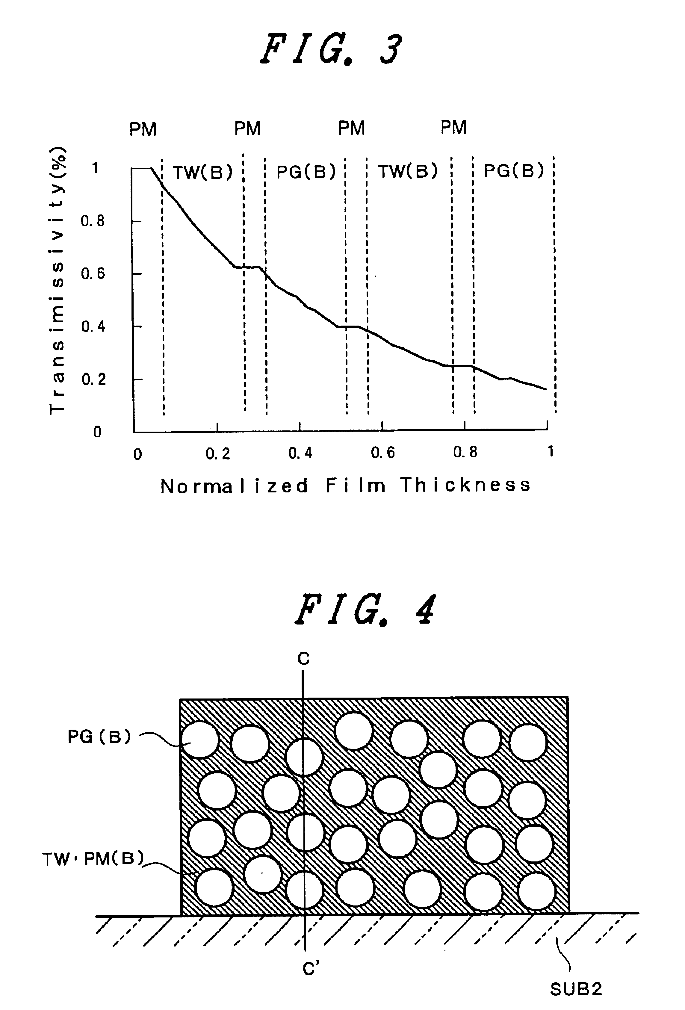
The second embodiment is suited to color filters for a transparent-type liquid crystal display device in which the number of particles of the B pigment PG(B) per unit volume can be made large (thick-color display).

FIG. 6 is an explanatory view showing the relationship between the transmissivity and the normalized film thickness of the color filter shown in FIG. 4. In FIG. 4, it is assumed that the B pigment PG(B) is present in the state of being averagely dispersed in the solid solution TW.PM(B) of polymer and wavelength converting material.

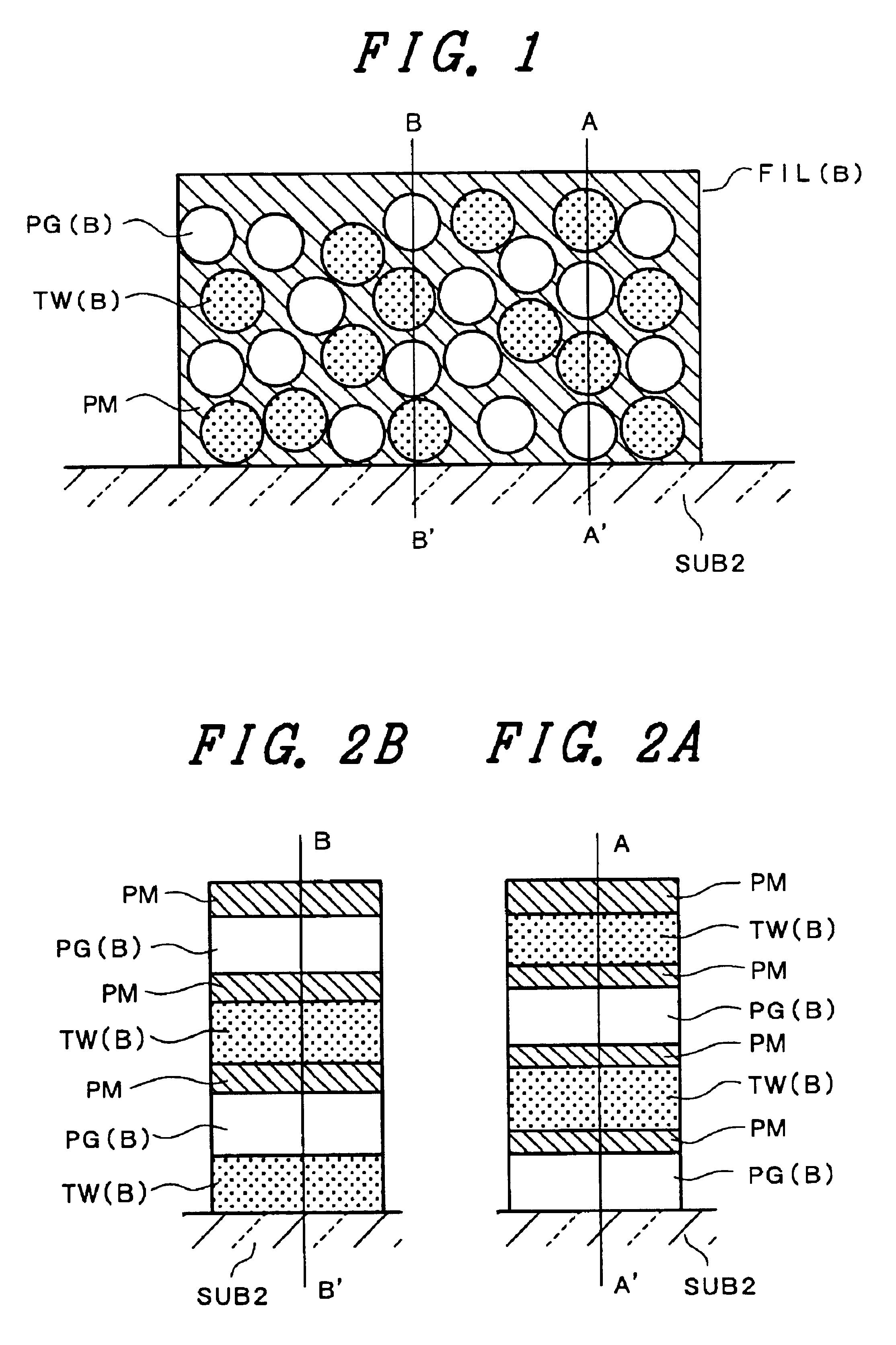
In the above-described first embodiment shown in FIG. 3, the color-converting material TW(B) is dispersed in the polymer PM together with the B pigment PG(B) as the particles of the blue fluorescent pigment, so that the optical transmissivity of the color filter in the thickness direction thereof varies in a staircase-shaped manner. In the second embodiment, since the color-converting material TW(B) is dissolved to form solid solution in the soli...

third embodiment

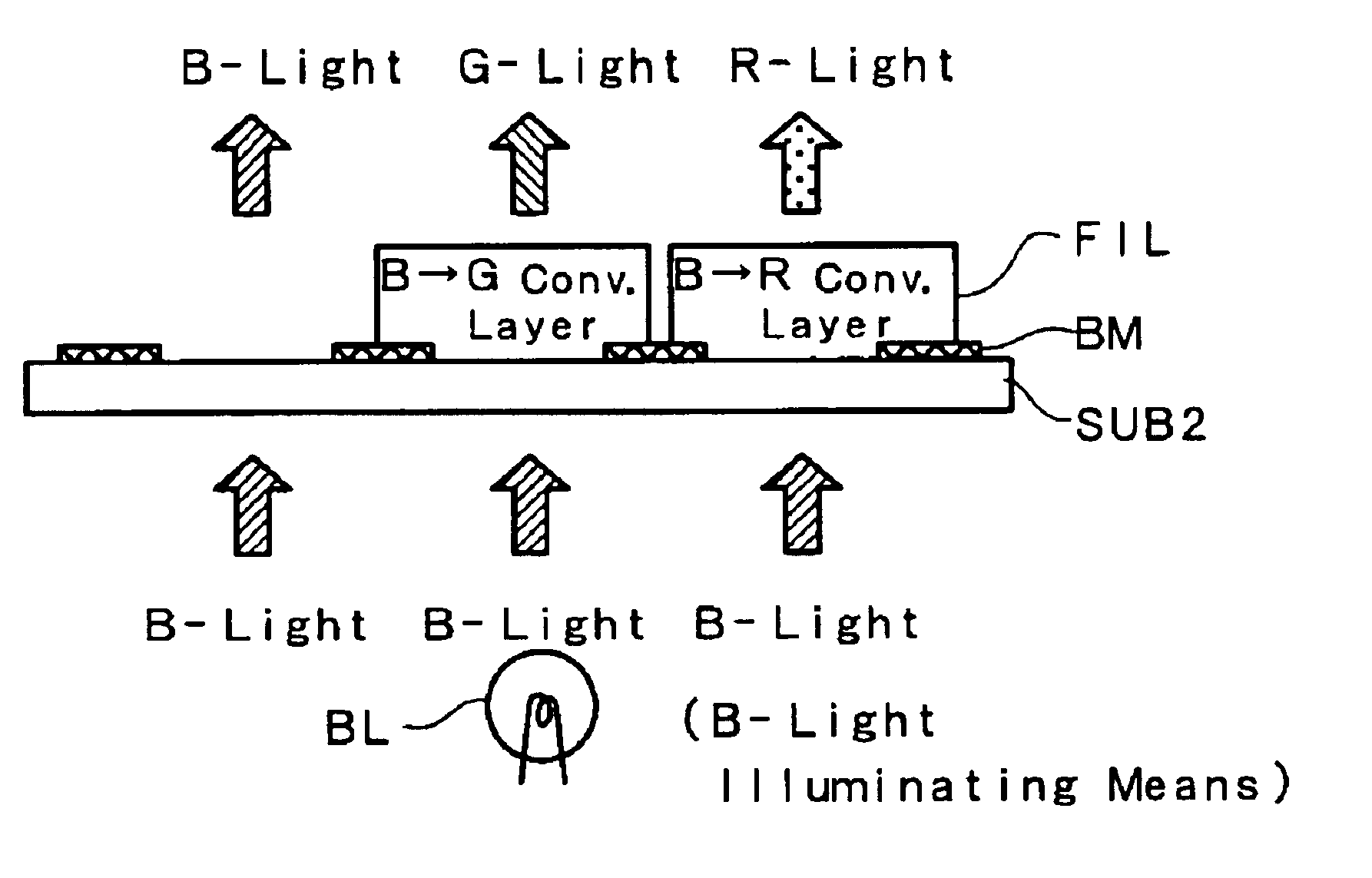
FIG. 11 is a cross-sectional view for diagrammatically explaining the construction of a color filter for the liquid crystal display device according to the invention. This color filter FIL uses an illuminating device (backlight) BL for emitting only one primary color, and areas each having a color-converting material for absorbing light in the wavelength range emitted from this backlight BL and converting one of a plurality of primary colors in other wavelength ranges and areas having neither filter materials nor color-converting materials are arranged in the color filter FIL.

Assuming that the plurality of primary colors are three colors R, G and B, three kinds of areas are formed on the inner surface of the upper glass substrate SUB2; one is an area of a B G converting layer containing a color-converting material which converts blue light (hereinafter, B-light) into green light (hereinafter, G-light), another is an area of a B R converting layer containing a color-converting materi...

fourth embodiment

FIG. 13 is a cross-sectional view for diagrammatically explaining the construction of a color filter for the liquid crystal display device according to the invention. This color filter FIL uses W-light illuminating means BL(W) for emitting light in a frequency range which covers all of red R, green G and blue B, and areas each having a color-converting material for absorbing light (W) in the wavelength range emitted from this backlight BL and converting one of a plurality of primary colors in other wavelength ranges are arranged in the color filter FIL.

Assuming that the plurality of primary colors are three colors R, G and B, three kinds of areas are formed on the inner surface of the upper glass substrate SUB2; one is an area of a W B converting layer containing a color-converting material which converts W-light into B-light, another is an area of a W G converting layer containing a color-converting material which converts W-light into G-light, and the other is an area of a W R con...


PUM

PropertyMeasurementUnit
thickaaaaaaaaaa
particle diameteraaaaaaaaaa
particle sizesaaaaaaaaaa

Abstract

In a liquid crystal display device comprising color filters therein, the present invention provides a color-converting material in at least one of the color filters which converts a part of an incident light of the at least one of the color filters into a light in a specific wavalength range together with a filter material passing the light in the specific wavelength range, so as to prevent deterioration of color purity of the light emitted thereby and to improve efficiency of optical utilization therein.

Description

BACKGROUND OF THE INVENTION1. Field of the InventionThe present invention relates to a liquid crystal display device capable of providing color display and, more particularly, to a liquid crystal display device using novel color filters which are improved in the efficiency of utilization of light.2. Description of the Related ArtLiquid crystal display devices are widely used as high-resolution display terminals for notebook type computers and computer monitors. Liquid crystal display devices are remarkable in technological advance, and have been able to provide display qualities which are close to those of CRTs. However, the liquid crystal display devices have not yet been satisfactory in terms of kinetic image display, color reproducibility and brightness, and also have the problem that a further reduction in manufacturing cost is needed.The liquid crystal display devices are classified into a simple matrix type in which multiple pairs of electrodes which intersect each other are f...

Claims


Application Information

Patent Timeline
Patent Type & Authority Patents(United States)
IPC IPC(8): G02F1/1335G02F1/13G09G3/36G02F1/133G02F1/13357G09G3/20
CPCG02F1/133617G02F1/13452G09G3/3611G02F1/1362G02F1/13454G09G3/3688G09G3/3614G09G3/3648G09G2310/027G09G2310/0289G09G2310/0297G09G3/36
Inventor HAMAMOTO, TATSUOTOMITA, YOSHIFUMITSUBOKA, TOMOAKIHIROSHIMA, MINORU
Owner PANASONIC LIQUID CRYSTAL DISPLAY CO LTD
Why Eureka
Try Eureka