Multiple antenna array with high isolation

a multi-antenna array and isolation technology, applied in the field of antennas, can solve the problems that the antenna transmitting/receiving element having only 15 db of isolation may not achieve the most effective beam steering or adaptive steering

Active Publication Date: 2008-06-10
TYCO ELECTRONICS LOGISTICS AG (CH)
View PDF4 Cites 39 Cited by
  • Summary
  • Abstract
  • Description
  • Claims
  • Application Information

AI Technical Summary

Problems solved by technology

However, antenna transmitting / receiving elements having only 15 dB of isolation may not achieve the most effective beam steering or adaptive steering, especially with elements having the same individual directional pattern.

Method used


Image

  • Multiple antenna array with high isolation
  • Multiple antenna array with high isolation
  • Multiple antenna array with high isolation

Examples


Embodiment Construction

[0023]As used herein, an element or step recited in the singular and proceeded with the word “a” or “an” should be understood as not excluding plural said elements or steps, unless such exclusion is explicitly stated. Furthermore, references to “one embodiment” of the present invention are not intended to be interpreted as excluding the existence of additional embodiments that also incorporate the recited features. Moreover, unless explicitly stated to the contrary, embodiments “comprising” or “having” an element or a plurality of elements having a particular property may include additional such elements not having that property.

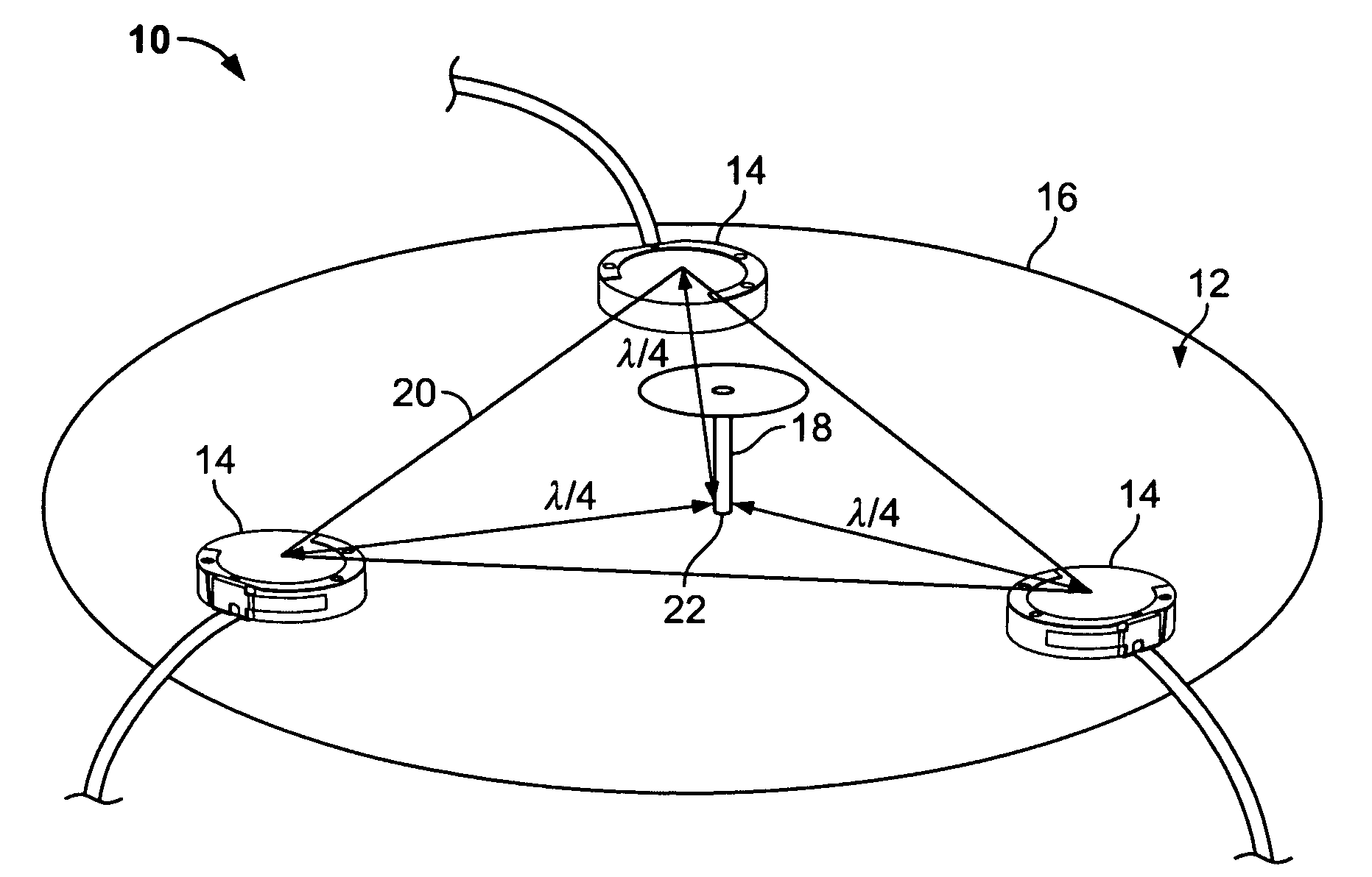
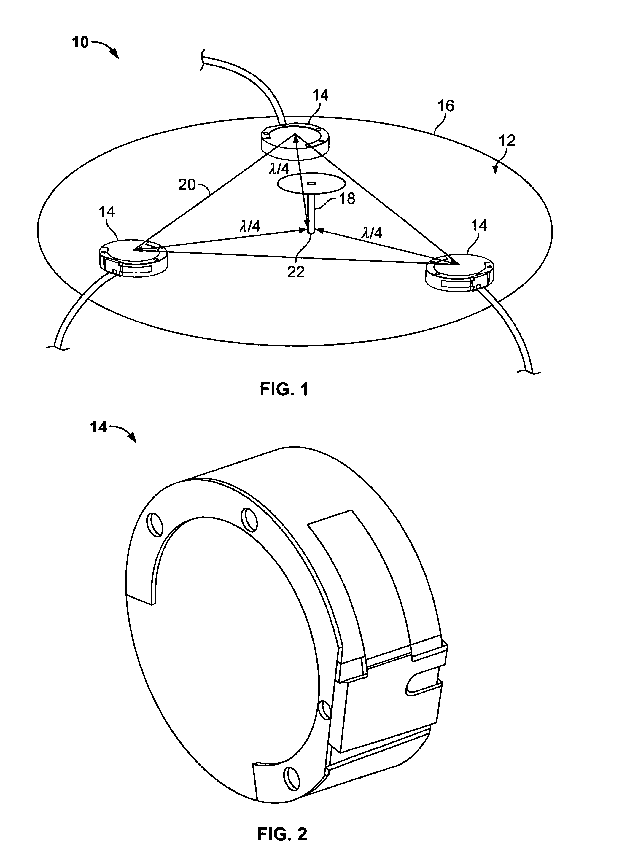
[0024]In some configurations of the present invention and referring to FIG. 1, a high-isolation, multiple in, multiple out (MIMO) antenna array 10 is provided. Array 10 can include a ground plane 12 and a plurality of antenna transmitting / receiving elements 14 arranged near a periphery 16 of ground plane 12. Each of the plurality of antenna transmitting / rece...


PUM


Abstract

A high-isolation multiple in, multiple out (MIMO) antenna array includes, in one configuration, a ground plane, and a plurality of antenna transmitting/receiving elements arranged near the periphery of the ground plane, wherein each of the antenna transmitting/receiving elements is resonant at a frequency f. Also, the array includes an isolation antenna element located on the ground plane, between the plurality of antenna transmitting/receiving elements. The isolation antenna element is also resonant at the same frequency f. The plurality of antenna transmitting/receiving elements and the resonant isolation antenna element are arranged on the ground plane arranged so as to achieve substantially greater than 15 dB isolation of the antenna transmitting/receiving elements. In some configurations, at least about 30 dB of isolation of the antenna transmitting/receiving elements can be achieved.

Description

BACKGROUND OF THE INVENTION[0001]This invention relates generally to antennas for the transmission and reception of radio frequency (RF) energy, and more particularly to methods and apparatus providing high isolation between transmitting / receiving elements of multiple element antenna arrays.[0002]Multiple in, multiple out (MIMO) antenna system are sometimes used in wireless computer networks such as local area networks (LANs) or WI-FI service. A MIMO antenna system combines the antennas by controlling phase differences and / or amplitude or gain differences between the antennas. This combination is used to form different beam shapes to eliminate interference and / or to enhance a signal in a selected direction. Thus, a MIMO antenna system is, to some degree, similar to an adaptive array.[0003]The antenna transmitting / receiving elements used in a MIMO array may inherently have 15 DB of isolation. Any combination of the transmitting / receiving elements can be used for receiving or transmit...

Claims


Application Information

Patent Timeline
Patent Type & Authority Patents(United States)
IPC IPC(8): H01Q21/00H01Q19/00
CPCH01Q1/52H01Q9/0421H01Q9/16H01Q21/28
Inventor BISHOP, BRUCE FOSTER
Owner TYCO ELECTRONICS LOGISTICS AG (CH)
Why Eureka
Try Eureka