Watch with metallic case including an electronic module for storing data, and electronic module for such a watch
a watch and electronic module technology, applied in the direction of timers, electromechanical clocks, time indications, etc., can solve the problems of increasing the cost of the watch, increasing the volume, and not being suitable for watches with any type of cas
- Summary
- Abstract
- Description
- Claims
- Application Information
AI Technical Summary
Benefits of technology
Problems solved by technology
Method used
Image
Examples
first embodiment
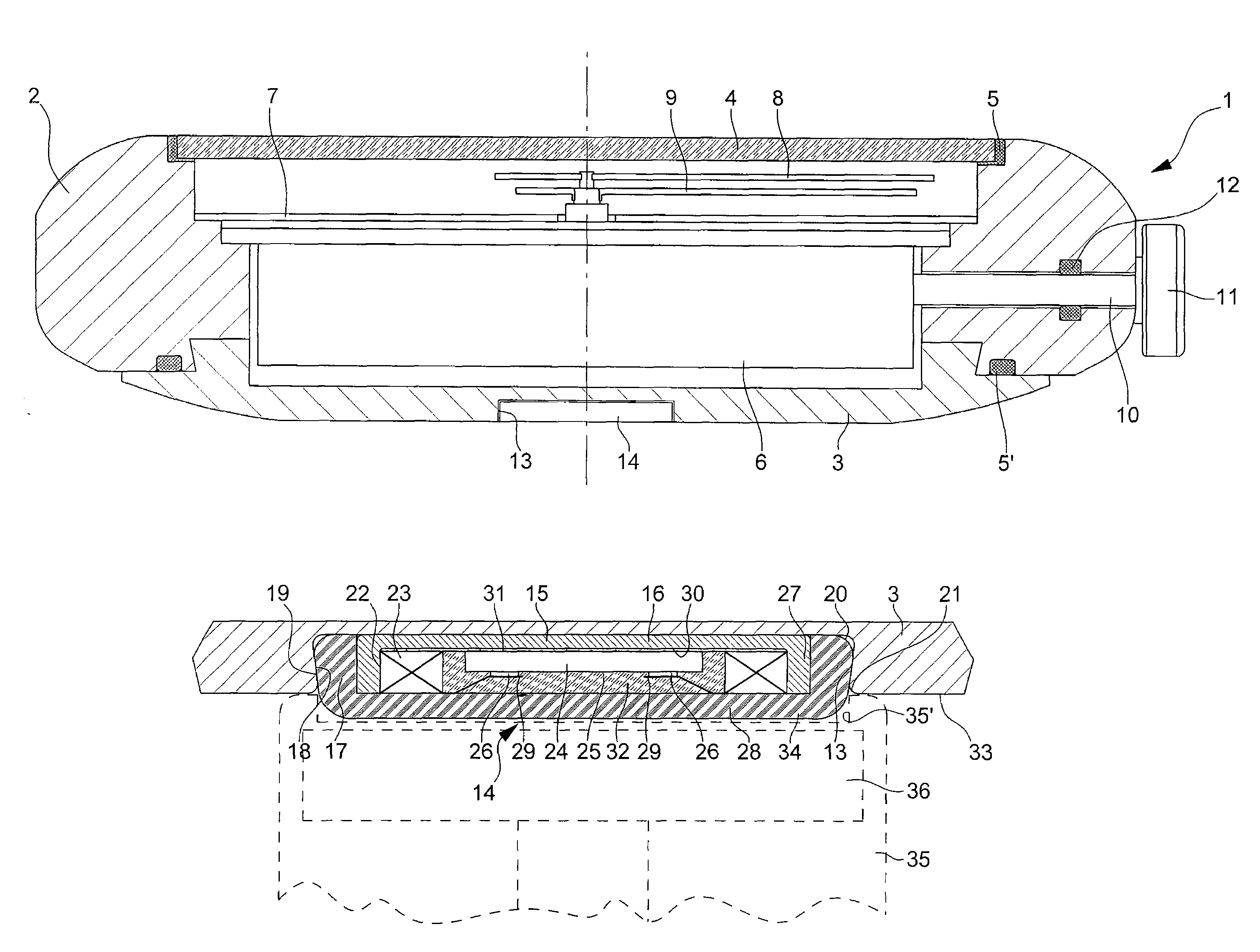
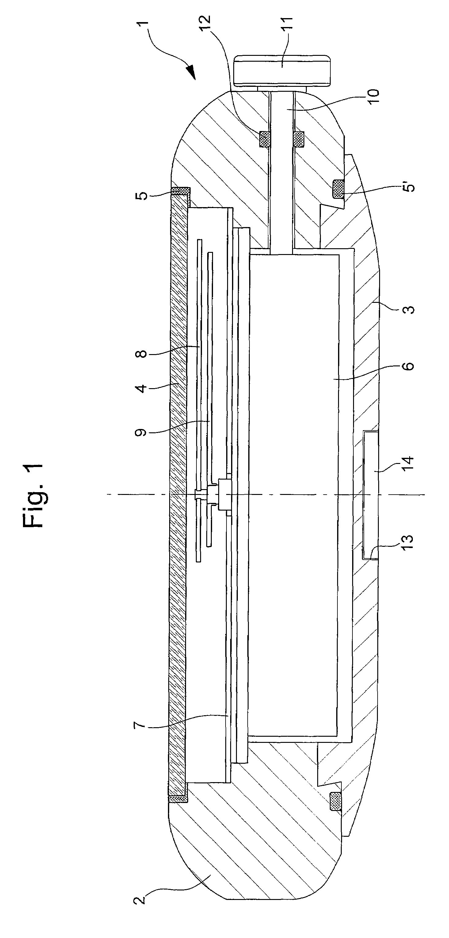
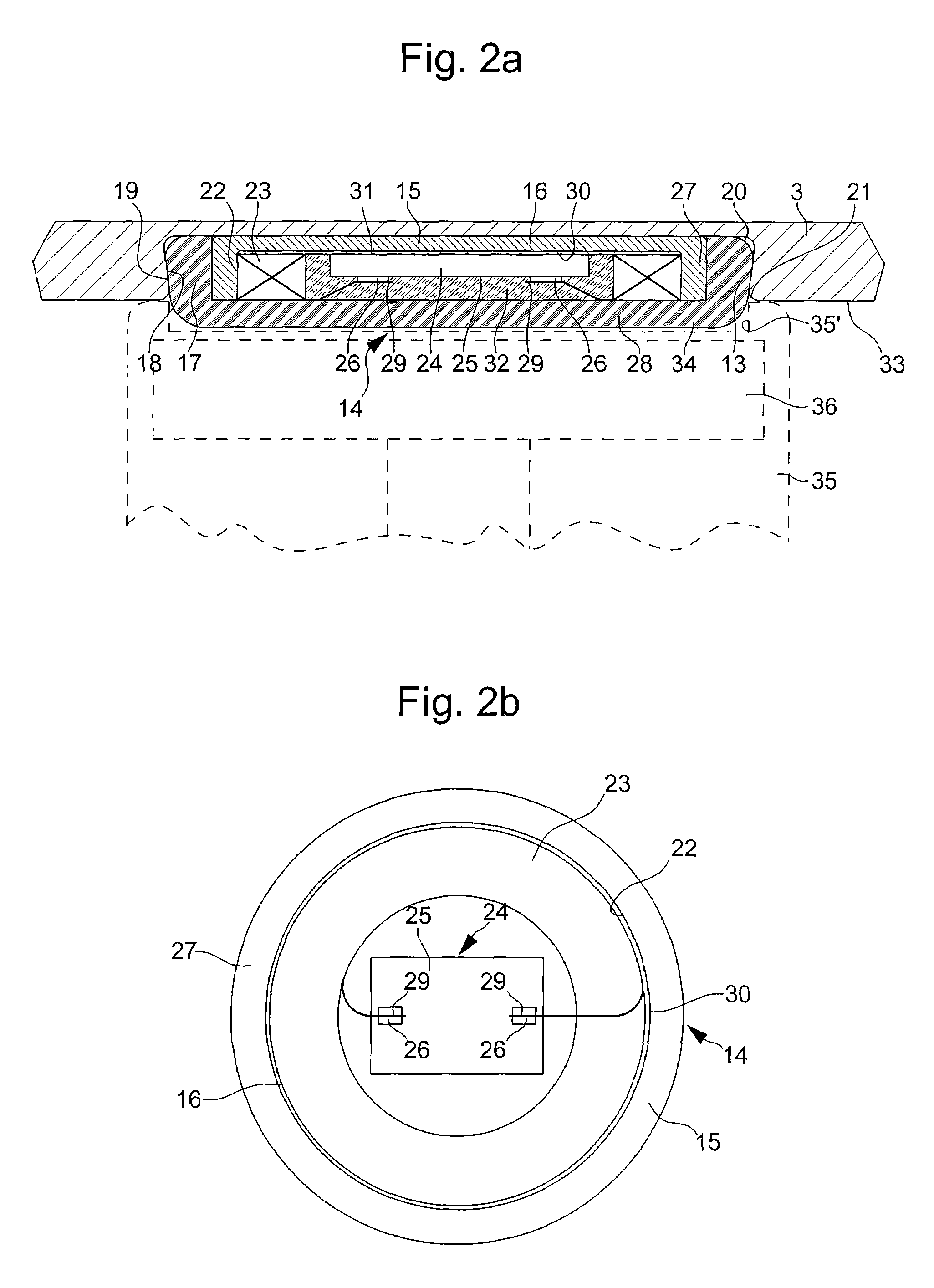
[0037]FIG. 2a is an enlarged cross-section of the area of the back cover 3 of the case 1 of FIG. 1 which shows electronic module 14 which can be inserted in a durable manner in cavity 13 of the back cover.
[0038]In this embodiment, module 14 mainly includes a base 15 on which are mounted a coil 23 acting as antenna for data communication and an integrated circuit chip 24 connected to the coil. The base is a metallic element that conducts magnetic flux to insulate coil 23 of the module magnetically when it is housed in cavity 13 of back cover 3 of the metallic case. The base 15 is in the form of a dome and has a flat bottom 16 and an essentially cylindrical lateral wall 27 to surround the coil on two sides. The dome shaped base is mounted in said cavity such that the flat bottom 16 is arranged between the bottom of cavity 13 and coil 23 mounted on said base. Bottom 16 of the base can come into contact with the bottom of cavity 13.
[0039]A protective cover 28, which includes a bottom an...
second embodiment
[0066]FIG. 3 is a similar view to FIG. 2a which shows the electronic module of a watch according to the invention. In this Figure, the same elements are designated by the same references and only new parts are indicated by new references.
[0067]One of the differences of this second embodiment in relation to that shown in FIG. 2a is that coil 23 and circuit 24 are no longer directly bonded onto the inner face 30 of bottom 16 of base 15, but on the substrate of a printed circuit 38. This substrate could also be bonded onto bottom 16 of base 15 of module 14 or simply driven inside the base.
[0068]The other difference is due to the fact that the ends of wire 19 of coil 23 no longer directly connect the coil to bumps 26 of integrated circuit chip 24 but via connection bumps 40 formed on the substrate of printed circuit 38. More specifically, each end of wire 29 is bonded or fixed by thermocompression or bonded by means of an electrically conductive adhesive onto one of bumps 40 and the lat...
third embodiment
[0071]In this third embodiment, the metallic base 15 is a rigid plate, which carries coil 23 and integrated circuit chip 24. The base is inserted in cover 28 in order to enclose said coil and said chip. As for the previous embodiments described hereinbefore, the base is positioned between the coil and the bottom of cavity 13 to magnetically shield the coil. However, base 15 only covers one surface of the coil and is thus less efficient than the dome-shaped base described hereinbefore. This rigid plate 15 can have a slightly greater external diameter than that of coil 23.
[0072]This embodiment is better suited when back cover 3 of the case and / or cover 28 of module 14 are formed of hard materials that are difficult to machine or shape.
[0073]Moreover, in this third embodiment as in those of FIGS. 2a and 2b, the wire ends 29 of coil 23 are directly fixed onto bumps 26 of integrated circuit chip 24, but it is clear that these wire ends and bumps 26 could be connected in the same way as i...
PUM
 Abstract
Description
Claims
Application Information
 - R&D
- Intellectual Property
- Life Sciences
- Materials
- Tech Scout
- Unparalleled Data Quality
- Higher Quality Content
- 60% Fewer Hallucinations
Browse by: Latest US Patents, China's latest patents, Technical Efficacy Thesaurus, Application Domain, Technology Topic, Popular Technical Reports.
© 2025 PatSnap. All rights reserved.Legal|Privacy policy|Modern Slavery Act Transparency Statement|Sitemap|About US| Contact US: help@patsnap.com


