Double layer patterning and technique for milling patterns for a servo recording head

a technology of patterning and servo recording head, which is applied in the direction of manufacturing head surface, maintaining head carrier alignment, and ensuring track following on tape, etc., can solve the problems of deterioration of tape and head, inability to provide a separate read head, and producing a relatively dirty environmen

Inactive Publication Date: 2008-06-17
ADVANCED RES
View PDF72 Cites 4 Cited by
  • Summary
  • Abstract
  • Description
  • Claims
  • Application Information

AI Technical Summary

Problems solved by technology

It is generally not feasible to provide a separate read head for each data track, therefore, the read head(s) must move across the width of the tape (in a translating direction), and center themselves over individual data tracks.
Both the tape and the head will deteriorate as a result of this frictional engagement; thus producing a relatively dirty environment.
As such, debris will tend to accumulate on the read head which in turn causes the head to wear even more rapidly.
Both the presence of debris and the wearing of the head have a tendency to reduce the efficiency and accuracy of the half track servo system.
While the above techniques are useful in producing timing based recording heads, they also limit the design characteristics of the final product.
Generally, these materials do not produce heads which have a high wear tolerance.
As such, these heads will tend to wear out in a relatively short time.
In addition, this class of materials have a low magnetic moment density (10 kGauss for NiFe), or saturation flux density, which limits their ability to record on very high coercivity media.
The second method also relies on plating for the top magnetic layer and is therefore limited to the same class of materials.
In addition, the use of ion milling makes the fabrication of such a head overly complex.
However, the traditional ion milling technique is rather imprecise and as the ions pass through that channel they are continuously being deflected.

Method used


Image

  • Double layer patterning and technique for milling patterns for a servo recording head
  • Double layer patterning and technique for milling patterns for a servo recording head
  • Double layer patterning and technique for milling patterns for a servo recording head

Examples


Embodiment Construction

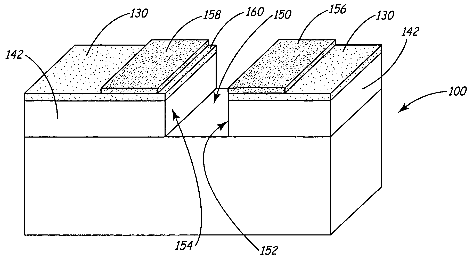
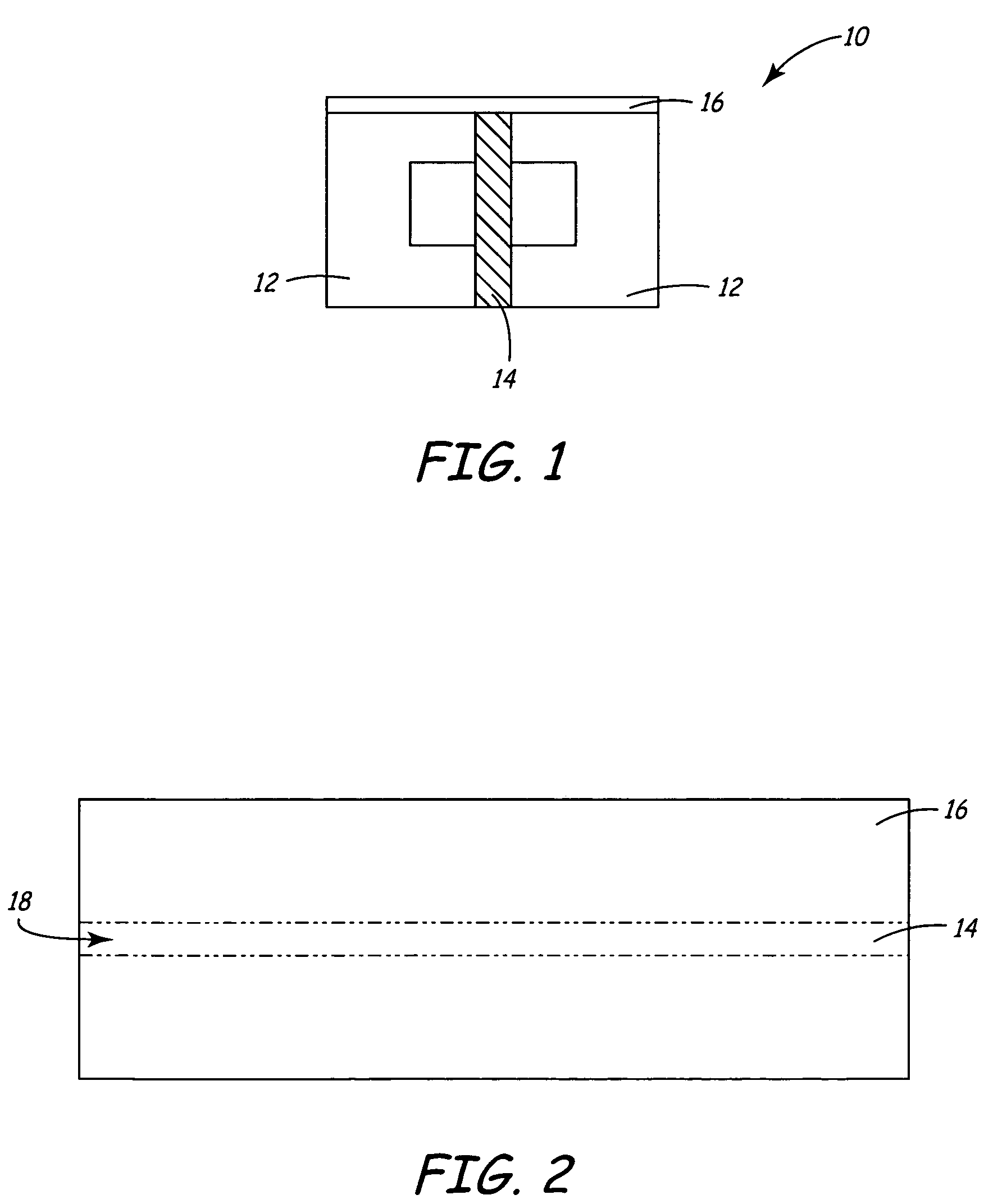
[0054]The present invention is a method of making a thin film magnetic recording head using a focused ion beam (FIB) to mill out gaps in the tape bearing surface. Referring to FIG. 1, a substrate 10 is created by glass bonding two C-shaped ferrite blocks 12 to a medially disposed ceramic member 14. The sizes and relative proportions of the ferrite blocks 12 and ceramic member 14 may vary as dictated by the desired parameters of the completed recording head. Furthermore, the choice of materials may also vary so long as blocks 12 remain magnetic while member 14 remains generally magnetically impermeable.

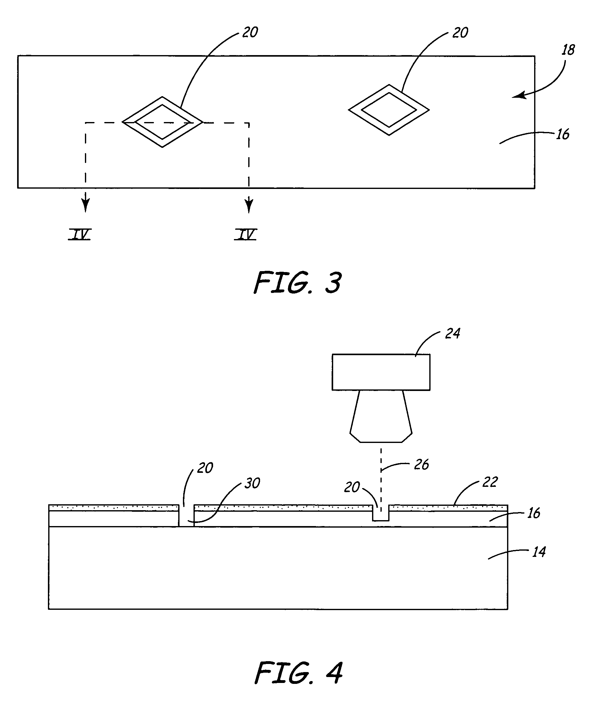
[0055]A layer of magnetically permeable material is deposited as a thin film 16 across an upper surface of each of the ferrite blocks 12, as well as the upper surface of the ceramic member 14. The magnetically permeable thin film 16 will become the tape bearing and data writing surface for the magnetic head 5 (see FIGS. 12 & 13). As such, it is desirable to form the layer of thin film ...


PUM

PropertyMeasurementUnit
thicknessaaaaaaaaaa
thicknessaaaaaaaaaa
areaaaaaaaaaaa

Abstract

Double photolithography is used to produce an under-layer of protective and filtering photoresist over a substrate that will have channels milled with a FIB. Secondary layers are applied with precision on top of the first layer in order to define the precise patterns to be milled and to provide targeting and alignment fiducials.

Description

CROSS REFERENCE TO RELATED APPLICATIONS[0001]This Application is a continuation of U.S. Ser. No. 10 / 298,764, filed Nov. 18, 2002, now abandoned which is a Continuation-in-Part of U.S. Ser. No. 09 / 922,546, filed on Aug. 3, 2001, now issued as U.S. Pat. No. 6,678,116, which is a Continuation of U.S. Ser. No. 09 / 255,762, filed on Feb. 23, 1999, now issued as U.S. Pat. No. 6,269,533, the contents of which are incorporated herein by reference.FIELD OF THE INVENTION[0002]This invention relates generally to magnetic recording heads and to a method of making thin-film magnetic heads for imprinting time based servo patterns onto a magnetic media.BACKGROUND OF THE INVENTION[0003]While a variety of data storage mediums are available, magnetic tape remains a preferred forum for economically storing large amounts of data. In order to facilitate the efficient use of this media, magnetic tape will have a plurality of data tracks extending in a transducing direction of the tape. Once data is record...

Claims


Application Information

Patent Timeline
Patent Type & Authority Patents(United States)
IPC IPC(8): G11B5/127H04R31/00G03F9/00G03F7/00G03F7/09G11B5/187G11B5/23G11B5/29G11B5/31G11B5/58G11B5/584H01L21/027
CPCG03F7/00G11B5/1276G11B5/23G11B5/232G11B5/3116G11B5/3163G11B5/58G11B5/584Y10T29/49039G11B5/295G11B5/3133G11B5/3166G11B5/3183H01J2237/31755Y10T29/49163Y10T29/49043Y10T29/49046Y10T29/49048Y10T29/49041Y10T29/49032Y10T29/49117G03F7/094
Inventor DUGAS, MATTHEW P.TERSTEEG, JOSEPH
Owner ADVANCED RES
Why Eureka
Try Eureka