Thermal mass flow transducer including PWM-type heater current driver

Active Publication Date: 2008-06-17
HONEYWELL INT INC
View PDF25 Cites 61 Cited by
  • Summary
  • Abstract
  • Description
  • Claims
  • Application Information

AI Technical Summary

Benefits of technology

[0006]In one exemplary embodiment, a thermal mass flow transducer includes first and second constant current sources, a first temperature sensitive element, a second temperature sensitive element, a heater element, and a control circuit. The first and second constant current sources are each operable to supply a constant current. The first temperature sensitive element is coupled to receive the constant current supplied from the first constant current source and is configured, upon receipt thereof, to generate a first temperature signal representative of its temperature. The second temperature sensitive element is coupled to receive the constant current supplied from the second constant current source and is configured, upon receipt thereof, to generate a second temperature signal representative of its temperature. The heater ele

Problems solved by technology

The relatively large energy dissipation by the DC-type current driver results in a significant energy waste.
Moreover, this energy is dissip

Method used


Image

  • Thermal mass flow transducer including PWM-type heater current driver
  • Thermal mass flow transducer including PWM-type heater current driver
  • Thermal mass flow transducer including PWM-type heater current driver

Examples


Embodiment Construction

[0011]The following detailed description is merely exemplary in nature and is not intended to limit the invention or the application and uses of the invention. Furthermore, there is no intention to be bound by any theory presented in the preceding background or the following detailed description.

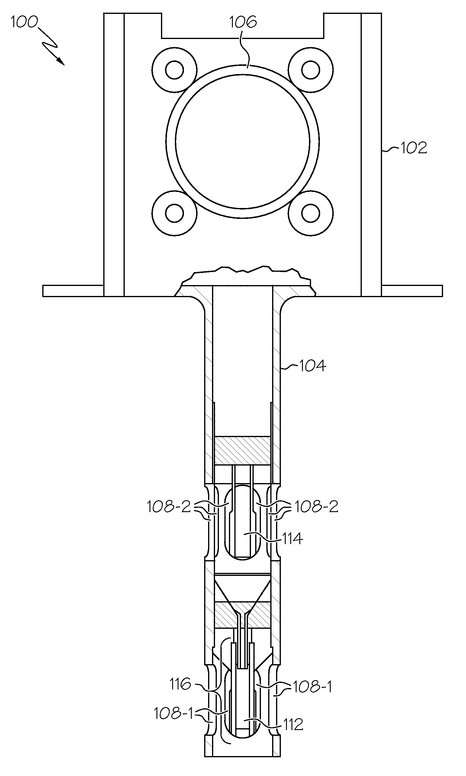
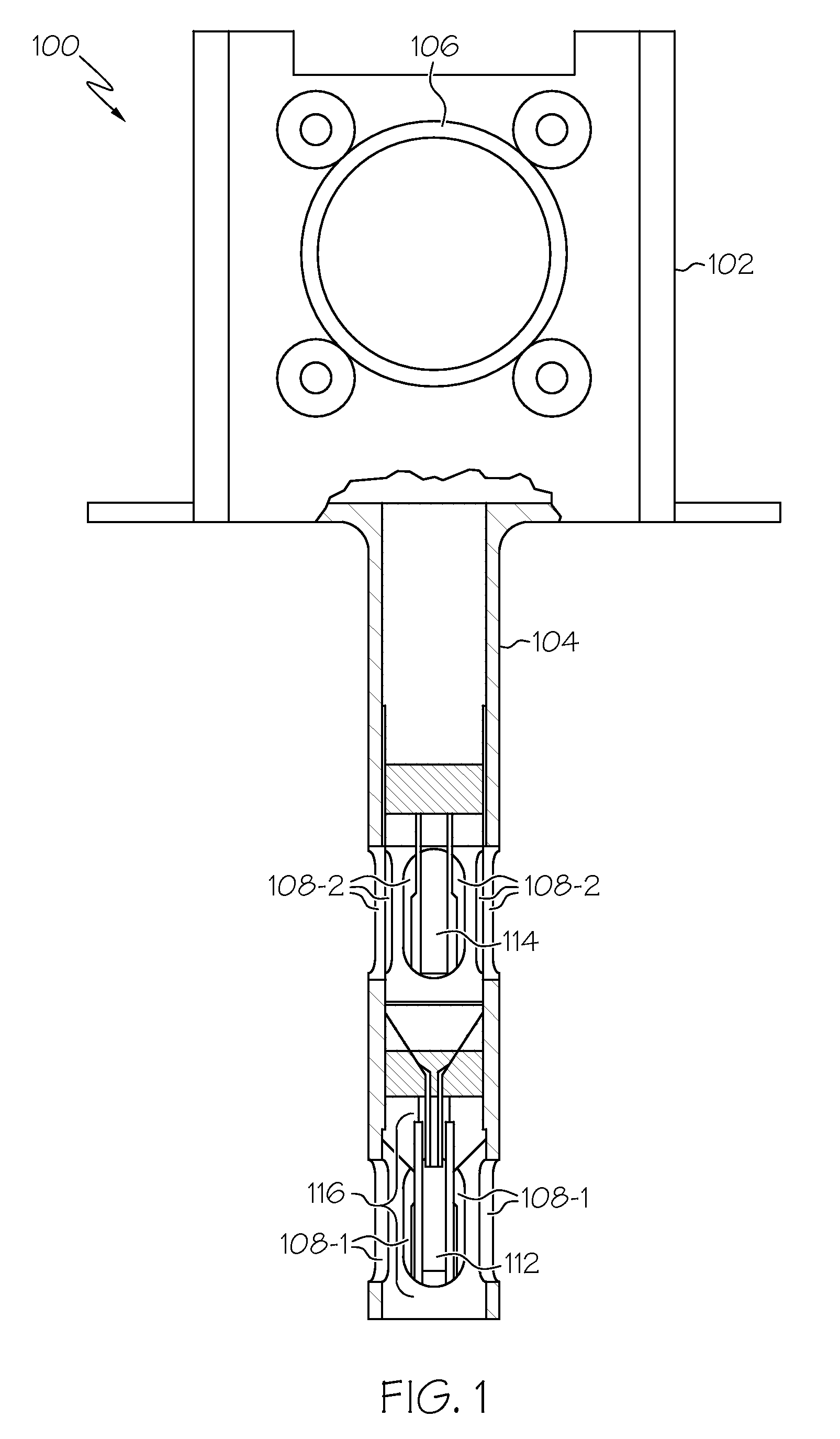
[0012]An exemplary physical implementation of a thermal mass flow transducer 100 is depicted, in partial cross section, in FIG. 1, and includes a housing 102 and a probe 104. The housing 102 is coupled to the probe 104 and is preferably configured to mount a fluid flow duct. The housing 102 preferably houses various circuitry, such as the circuitry described further below, and includes a connector 106 that is preferably coupled to the circuitry via non-illustrated leads. Various other non-illustrated leads extend through a non-illustrated opening in the housing 102 and into the probe 104.

[0013]The probe 104 extends from the housing in cantilever fashion, and has first and second sets of flow...


PUM


Abstract

A thermal mass flow transducer includes first and second constant current sources, a first temperature sensitive element, a second temperature sensitive element, a heater element, and a control circuit. The control circuit is coupled to the heater element and is further coupled to receive temperature signals from the first and second temperature sensitive element. The control circuit is responsive to the temperature signals to determine a temperature difference between the first and second temperature sensitive elements, to generate a pulse width modulation (PWM) current based on the determined temperature difference, and to supply the current to the heater element at a current magnitude sufficient to maintain the temperature difference at a predetermined value.

Description

TECHNICAL FIELD[0001]The present invention generally relates to fluid flow transducers and, more particularly, to a thermal mass flow transducer heater control circuit current driver.BACKGROUND[0002]Fluid flow sensing and control systems are included in various systems, devices, and environments. For example, many aircraft rely on accurate airflow sensing and control for various performance and environmental functions, such as engine starting, equipment cooling, and cockpit and cabin environmental control. No matter the particular end-use, typical flow sensing and control systems include one or more flow transducers to sense the mass flow rate of the fluid being controlled, and supply a signal representative of the sensed flow to a control law. The control law may then command one or more flow control devices, such as one or more valves, to a appropriate position to achieve a desired fluid flow rate.[0003]One particular type of flow transducer that has been and continues to be used ...

Claims


Application Information

Patent Timeline
IPC IPC(8): G01F1/68
CPCG01F1/6842G01F1/696G01F1/698
Inventor KORNIYENKO, OLEGYANKOVSKIY, BORISSTOIANOV, GABRIEL
Owner HONEYWELL INT INC
Why Eureka
Try Eureka