Control apparatus for hydraulic cylinder

a control apparatus and hydraulic cylinder technology, applied in the direction of fluid couplings, servomotors, couplings, etc., can solve the problems of reducing the degree of freedom, the deceleration of the piston b>50/b> cannot be adjusted in accordance with a change, and the pressure rise of the cushion chamber. , to achieve the effect of reducing the speed of the piston and increasing the pressure of the cushion chamber

Inactive Publication Date: 2008-06-17
KYB CORP
View PDF16 Cites 33 Cited by
  • Summary
  • Abstract
  • Description
  • Claims
  • Application Information

AI Technical Summary

Benefits of technology

[0008]It is an object of the present invention to provide a control apparatus for a hydraulic cylinder which can freely control a cushion speed of a piston in accordance with a change of operating conditions.
[0010]When the piston enters into the piston stroke end range and thereby the pressure of the cushion chamber is increased, the controller detects that the piston enters into the piston stroke end range and then varies the opening degree of the control valve. As a result, the pressure of the operating oil in the oil chamber of the hydraulic cylinder is controlled to lower a piston speed. The pressure in the oil chamber can be freely adjusted in accordance with an opening degree of the control valve, which makes it possible to freely control a deceleration degree of the piston, namely cushion characteristics in accordance with operating conditions of the hydraulic cylinder.

Problems solved by technology

However, an extremely rapid cushion pressure rise reduces an absorption effect of the impact shock.
However, since in such conventional control apparatus of the hydraulic cylinder, the pressure adjustment unit is designed to adjust a discharge pressure of the hydraulic pump P in accordance with a cushion pressure without any other modulation, deceleration of the piston 50 can not be adjusted in accordance with a change of operating conditions, for example a speed of the piston 50 or the like.
This conventional control apparatus thus has the problem with reduction of degrees of freedom in a cushion pressure control.

Method used


Image

  • Control apparatus for hydraulic cylinder
  • Control apparatus for hydraulic cylinder
  • Control apparatus for hydraulic cylinder

Examples


Embodiment Construction

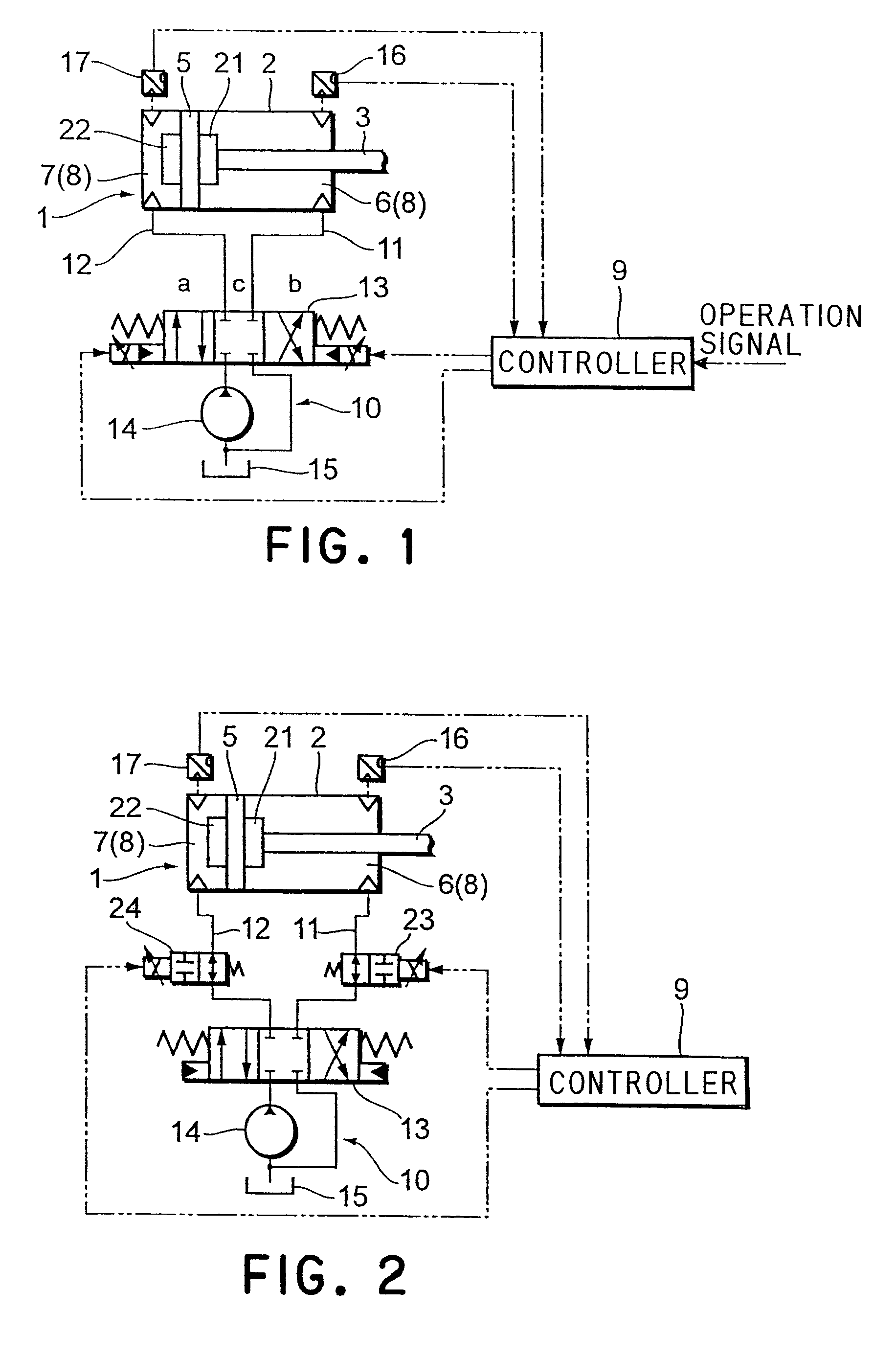
[0016]Embodiments according to the present invention will be described below with reference to the accompanying drawings.

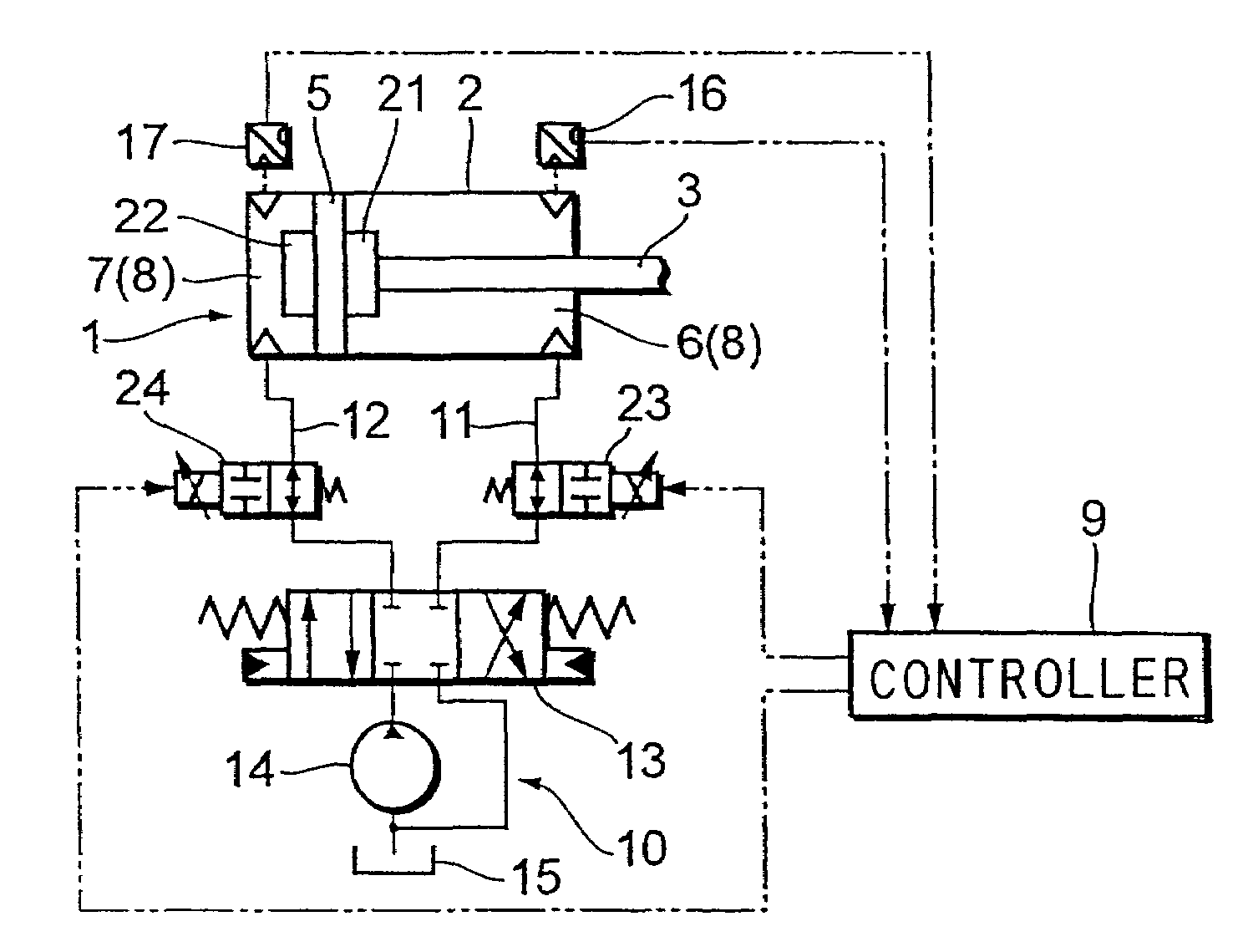
[0017]As shown in FIG. 1, a hydraulic cylinder 1 is equipped with a cylinder tube 2, a piston rod 3 extending from one end of the cylinder tube 2, a piston 5 connected to the piston rod 3 and sliding on an inner surface of the cylinder tube 2, and a head-side oil chamber 6 and a bottom-side oil chamber 7 divided by the piston 5.

[0018]The hydraulic cylinder 1 moves the piston 5 based upon a difference in pressure between each operating oil acting on both faces of the piston 5 to expand / contract the piston rod 3.

[0019]A hydraulic circuit 10 is connected to the oil chamber 6 and the oil chamber 7 of the hydraulic cylinder 1 for supplying and draining the operating oil. The hydraulic circuit 10 is equipped with supply / discharge passages 11, 12 connected to the oil chamber 6 and the oil chamber 7 and a control valve 13 to switch the supply / drain passages 11, 12 selecti...


PUM


Abstract

Cushion chambers (8) disposed in the vicinity of both ends of a hydraulic cylinder (1) to throttle inflow or outflow of an operating oil caused by a piston (5) moving close to a piston stroke end, pressure sensors (16, 17) to detect pressures in the cushion chambers (8), and a control valve (13) disposed in a passage to supply / drain the operating oil to and from oil chambers (6, 7) of the hydraulic cylinder (1) for varying a flow amount of the operating oil are provided. A controller (9) varies an opening degree of the control valve (13) within a piston stroke end range based upon outputs of the pressure sensors (16, 17), adjusts a cushion pressure and controls a moving speed of the piston (5). Thereby deceleration degrees of the piston (5) can be freely adjusted within the piston stroke end range based upon a change of the operating conditions of the hydraulic cylinder (1).

Description

CROSS-REFERENCE TO RELATED APPLICATIONS[0001]This application is a continuation of U.S. patent application Ser. No. 10 / 550,574 filed on Mar. 26, 2004 now abandoned.FIELD OF THE INVENTION[0002]This invention relates to a control apparatus for a hydraulic cylinder which can absorb an impact shock generated when a piston reaches a stroke end.RELATED ART[0003]Conventionally, there is, for example, such a type of control apparatus for a hydraulic cylinder as shown in FIG. 5. (refer to Japanese Unexamined Patent Publication No. 11-108014). FIG. 5 shows, for example a hydraulic drive circuit attached in a hydraulic power shovel that is provided with a hydraulic pump P supplying an operating oil, a hydraulic cylinder 51 including cushion mechanisms 61, 62 each disposed in both sides of a piston 50, a direction control valve 60 controlling flow of the operating oil supplied to the hydraulic cylinder 51 from the hydraulic pump P, and a pressure adjustment unit changing pressure of the operati...

Claims


Application Information

Patent Timeline
Patent Type & Authority Patents(United States)
IPC IPC(8): F15B15/22F01B31/12E02F9/22F15B11/00F15B11/048
CPCF15B11/048F15B15/222F15B21/08F15B2211/20538F15B2211/30525F15B2211/3111F15B2211/6313F15B2211/7053F15B2211/853
Inventor KOBATA, HIROSHICHRISTIANSON, ROLLIN C.KOLBE, CHRISTOPHER JOHN
Owner KYB CORP
Why Eureka
Try Eureka