
Paired air bar/hole bar arrangement in web dryer

a dryer and air bar technology, applied in the direction of dryers with progressive movements, furniture, lighting and heating apparatus, etc., can solve the problems of ink build-up in hard-to-float light-weight webs, inability to adjust the speed of the dryer, so as to improve the cushion pressure, reduce the speed, and improve the effect of flotation

Active Publication Date: 2013-12-31
DURR SYST INC
View PDF10 Cites 0 Cited by
  • Summary
  • Abstract
  • Description
  • Claims
  • Application Information

AI Technical Summary

Benefits of technology

This configuration ensures positive flotation with minimal web flutter, effective heat transfer, and reduced ink build-up, maintaining web quality even at high tensions without adding air horsepower requirements.

Problems solved by technology

When floating light weight webs under medium to high tensions, machine direction corrugations often form in the web which can not be removed with prior art dryer nozzle arrangements.
In addition, these hard-to-float light weight webs tend to have ink build up and marking problems when conventional nozzle arrangements are employed.

Method used


Image

  • Paired air bar/hole bar arrangement in web dryer
  • Paired air bar/hole bar arrangement in web dryer
  • Paired air bar/hole bar arrangement in web dryer

Examples


Embodiment Construction

[0019]Although the present invention is not limited to any particular flotation nozzle design, it is preferred that flotation nozzles which exhibit the Coanda effect such as the HI-FLOAT® air bar commercially available from Megtec, Inc. can be used, in view of their high heat transfer and excellent flotation characteristics. Standard 1× HI-FLOAT® air bars are characterized by a spacing between slots of 2.5 inches; a slot width of 0.070 to 0.075 inches, usually 0.0725 inches; an installed pitch of 10 inches; and a web-to-air bar clearance of ⅛ inch. Air bar size can be larger or smaller. For example, air bars ½, 1.5, 2 and 4 times the standard size can be used. Air bars 2 times the standard size are characterized by a slot distance of 5 inches and slot widths of 0.140 to 0.145 inches (available commercially as “2× air bars” from Megtec, Inc.). In general, the greater distance between the slots results in a larger air pressure pad between the air bar and the web, which allows for incr...


PUM


Abstract

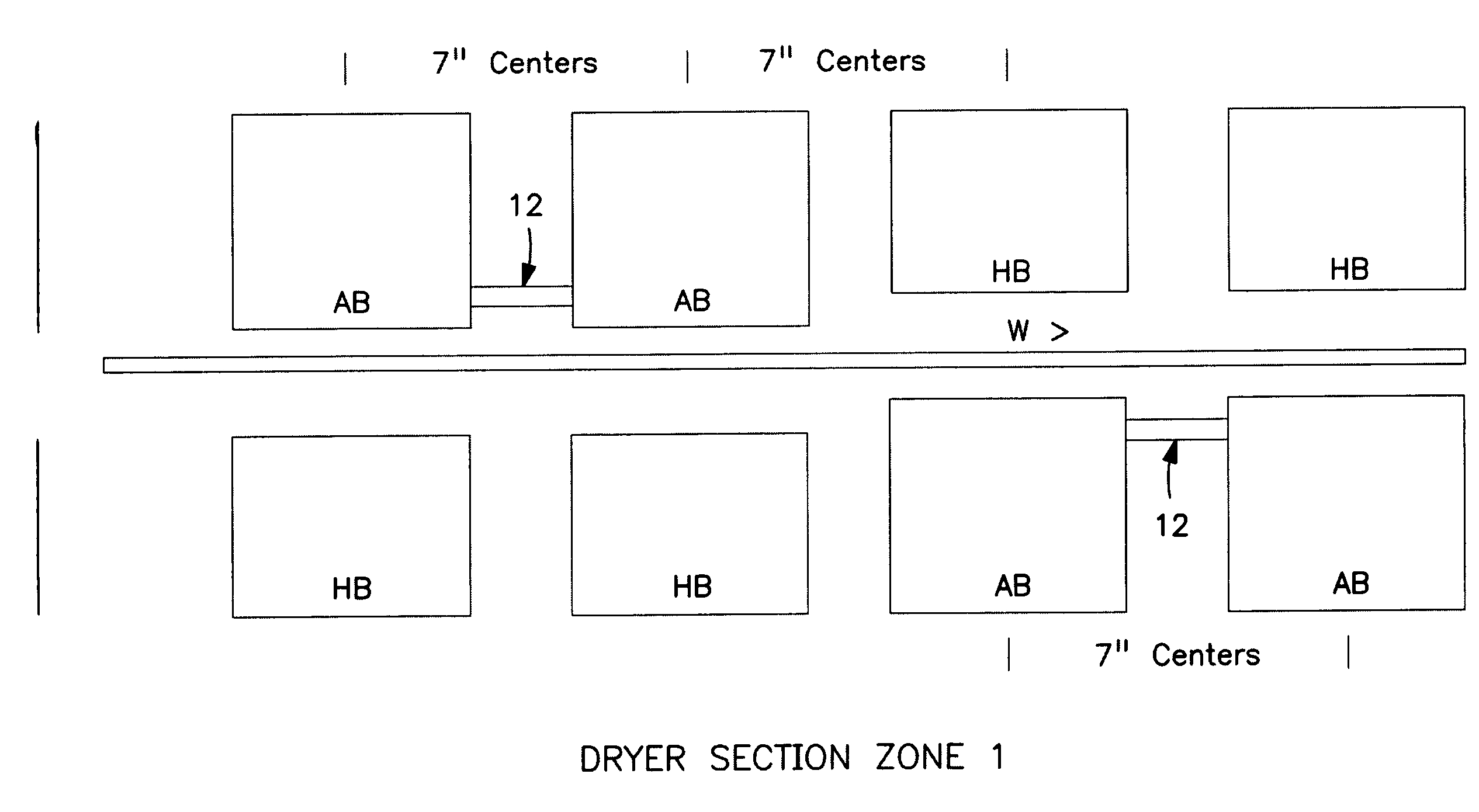
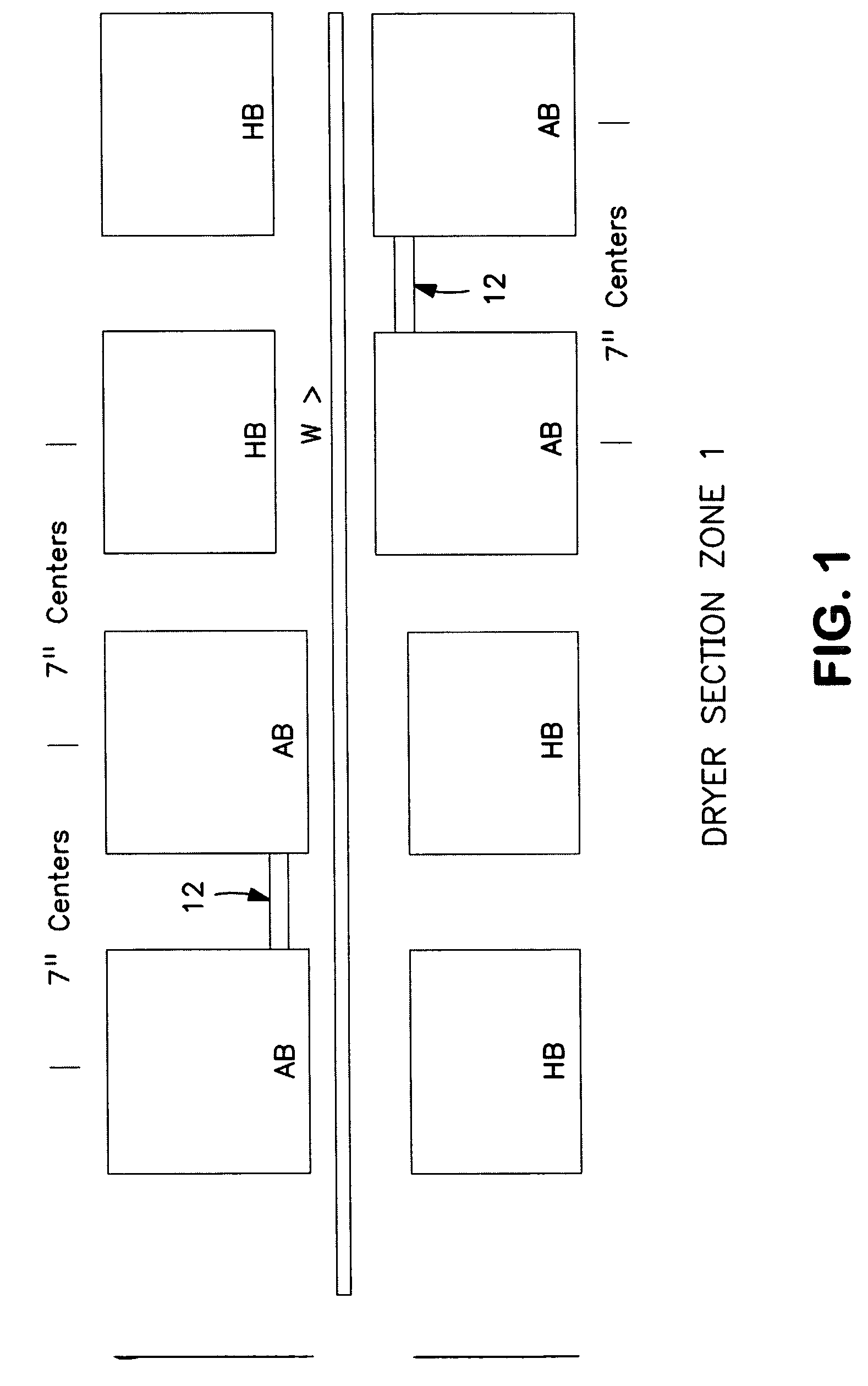
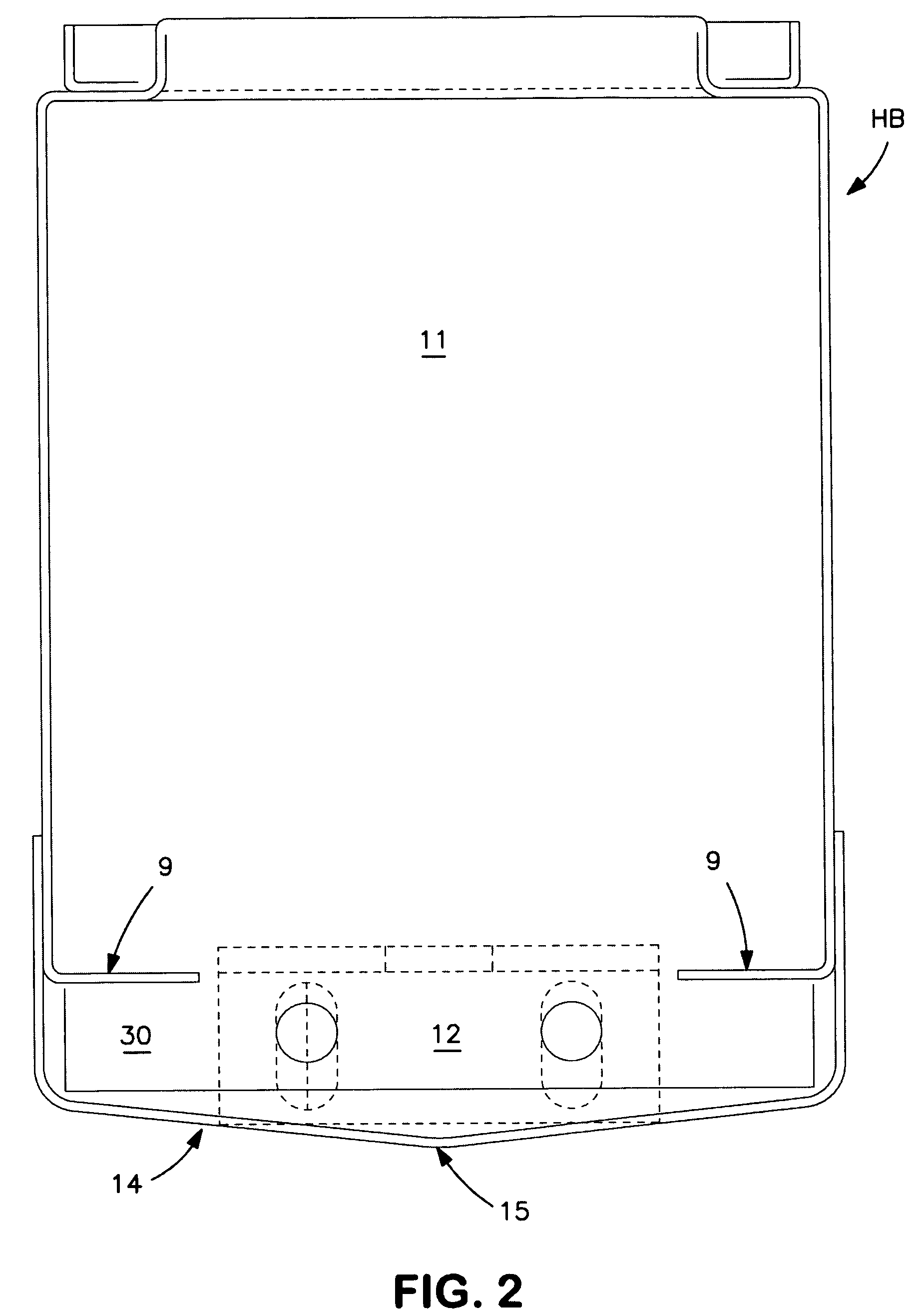
Apparatus and method for the non-contact drying of a web of material. The apparatus includes air flotation nozzles for floating the web, and direct air impingement nozzles for enhanced drying of the web. The nozzle arrangement is particularly well-suited to float and dry light weight webs under moderate to high tension. Increased cushion pressure is created to support the web preferably with the same horsepower as conventional arrangements. The increased cushion pressure pad of the nozzle arrangement allows for good flotation with reduced velocities below about 11,500 FPM. Machine direction wrinkles are removed and the result is positive flotation with no marking on the web or ink build up on the air bars. The nozzle arrangement includes pairs of flotation nozzles directly opposing pairs of direct impingement nozzles. A perforated member can be positioned between flotation nozzles within a pair of flotation nozzles to control return air.

Description

[0001]This application claims priority of U.S. Provisional Application Ser. No. 61 / 190,283 filed on Aug. 27, 2008, the disclosure of which is incorporated herein by reference.BACKGROUND OF THE INVENTION[0002]In drying a moving web of material, such as paper, film or other sheet material, it is often desirable to contactlessly support the web during the drying operation in order to avoid damage to the web itself or to any ink or coating on the web surface. A conventional arrangement for contactlessly supporting and drying a moving web includes upper and lower sets of air bars extending along a substantially horizontal stretch of the web. Heated air issuing from the air bars floatingly supports the web and expedites web drying. The air bar array is typically inside a dryer housing which can be maintained at a slightly sub-atmospheric pressure by an exhaust blower that draws off the volatiles emanating from the web as a result of the drying of the ink thereon, for example.[0003]When fl...

Claims


Application Information

Patent Timeline
Patent Type & Authority Patents(United States)
IPC IPC(8): F26B13/10
CPCF26B13/104
Inventor ROCHELEAU, MICHAEL, O.
Owner DURR SYST INC
Learn More