Optical receptacle having stub capable of enhancing optical coupling efficiency and optical module installing the same

a technology optical receptacle, which is applied in the direction of optics, optical light guides, instruments, etc., can solve the problems of reducing the coupling tolerance between the external fiber inserted into the receptacle and the guide fiber within the built-in ferrule, and achieve the effect of suppressing the degradation of optical coupling efficiency between the optical fiber and the laser diod

Active Publication Date: 2008-06-17
SUMITOMO ELECTRIC IND LTD
View PDF10 Cites 4 Cited by
  • Summary
  • Abstract
  • Description
  • Claims
  • Application Information

AI Technical Summary

Benefits of technology

[0008]The diameter of the first bore may be substantially equal to the diameter of the optical fiber at an interface between the first and second bores. Moreover, the diameter of the second bore is greater than that of the first bore. Accordingly, the light propagating in the optical fiber is not blocked by the stub, which suppresses the reduction of the optical coupling loss at the optical receptacle due to the misalignment between the core of the optical fiber and the waveguide, or the external force applied to the sleeve along the axial direction thereof.
[0009]The waveguide, integrated with the stub, may have a convex surface at a side opposite to the second bore. This enables the tip of the waveguide to come in physically contact to the optical fiber. Accordingly, a coupling loss derived from the Fresnel reflection at the contact may be reduced. Moreover, by setting the refractive index of the waveguide substantially equal to that of the optical fiber, the reflection at the contact may further reduced. The waveguide may be made of silica glass, which is the same material with the core of the fiber.
[0010]The interface between the first and second bores of the stub may be inclined with respect to the optical axis of the sleeve. Here, the optical axis of the sleeve is identical with that of the stub. This inclined surface at the interface may prevent the light from reflecting to the incoming direction, thereby suppressing the optical noise when the light-emitting device such as semiconductor laser diode is coupled with the optical receptacle.

Problems solved by technology

However, the conventional built-in ferrule provides a guide fiber, typically a single mode fiber, to guide light, which reduces coupling tolerance between the external fiber inserted into the receptacle and the guide fiber within the built-in ferrule.

Method used


Image

  • Optical receptacle having stub capable of enhancing optical coupling efficiency and optical module installing the same
  • Optical receptacle having stub capable of enhancing optical coupling efficiency and optical module installing the same
  • Optical receptacle having stub capable of enhancing optical coupling efficiency and optical module installing the same

Examples


Embodiment Construction

[0019]Next, preferred embodiments according to the present invention will be described as referring to accompanying drawings.

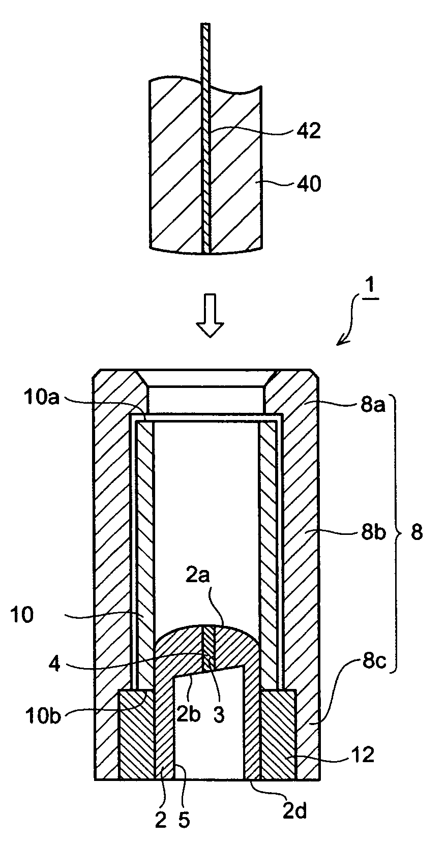
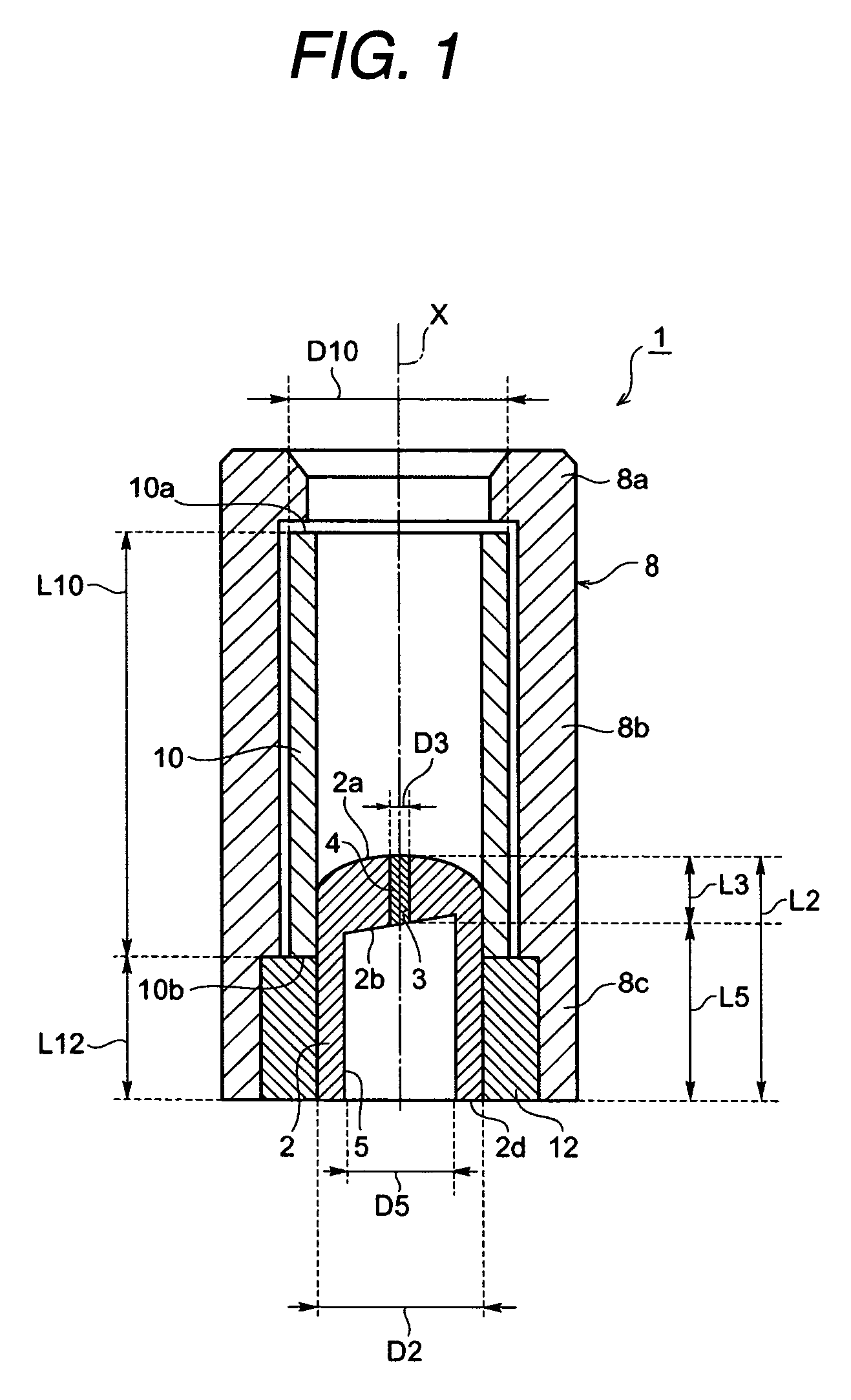
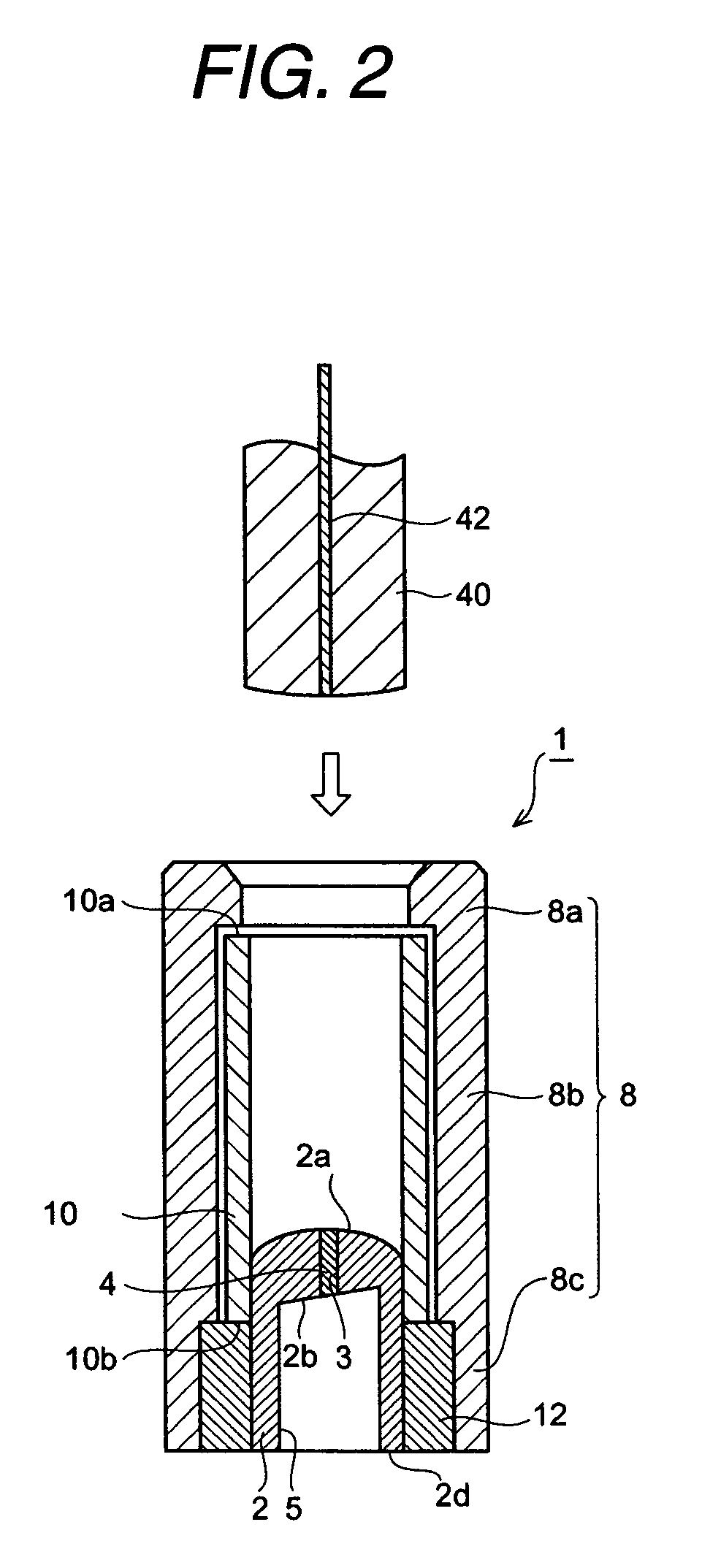
[0020]FIG. 1 is a cross section of an optical receptacle according to a first embodiment of the invention, and FIG. 2 is a cross section of the optical receptacle shown in FIG. 1 with an optical plug to be mated with an optical receptacle. As shown in FIGS. 1 and 2, the optical receptacle 1 comprises a stub 2, an optical waveguide 4, a sleeve cover 8, a sleeve 10, and a bush 12. The stub 2 supports the optical waveguide 4 by covering the outer surface of the waveguide 4. Specifically, the stub 2 extends along a longitudinal direction, the X-direction in FIG. 1, of the sleeve cover 8 with a cylindrical configuration. The stub 2 may be made of hard material, for instance ceramics such as zirconia or metal to secure the dimensional accuracy. When zirconia is applied, the stub 2 may be made of injection forming. The stub 2 has a length L2 about 3 mm and an outer d...


PUM


Abstract

The present invention provides an optical receptacle capable of reducing the optical coupling loss with the connector plug to be mated with the receptacle, and an optical module installing the receptacle. The receptacle of the invention includes an optical waveguide, a stub, and a body. The stub includes a first bore, into which the waveguide is disposed, and a second bore. The waveguide may be made of same material as that constituting the core of the optical fiber, and may have a substantially same diameter as that of the cladding. Thus, the aperture for coupling the optical fiber may be expanded.

Description

BACKGROUND OF THE INVENTION[0001]1. Field of the Invention[0002]The present invention relates to an optical receptacle with a stub that is capable of increasing the optical coupling efficiency with an optical fiber, and an optical module installing the optical receptacle.[0003]2. Related Prior Art[0004]As a conventional optical receptacle having the so-called co-axial shape, Japanese Patent published as H10-332988 has disclosed one typical configuration with a built-in ferrule securing an optical fiber therein. To mate an optical plug ferrule with the receptacle above may accomplish the optical coupling between the optical fiber and the optical device accompanied with the optical receptacle.[0005]However, the conventional built-in ferrule provides a guide fiber, typically a single mode fiber, to guide light, which reduces coupling tolerance between the external fiber inserted into the receptacle and the guide fiber within the built-in ferrule. Accordingly, the optical coupling chara...

Claims


Application Information

Patent Timeline
Patent Type & Authority Patents(United States)
IPC IPC(8): G02B6/36
CPCG02B6/4206
Inventor NAKANISHI, HIROMIFURUMAI, MASAKI
Owner SUMITOMO ELECTRIC IND LTD
Why Eureka
Try Eureka