Shoe press

a technology of shoe press and shoe body, which is applied in the direction of press section, non-fibrous pulp addition, calender, etc., can solve the problems of thermal expansion of shoe, hydraulic device or device used, and become pressurized

Inactive Publication Date: 2008-06-17
VALMET TECH INC
View PDF8 Cites 22 Cited by
  • Summary
  • Abstract
  • Description
  • Claims
  • Application Information

AI Technical Summary

Benefits of technology

[0009]The piston sealingly engages both the first and second cylinders. The first cylinder is urged away from the second cylinder when the actuator is pressurized. The spherical surfaces of the piston ends allow the piston to pivot about axes parallel to the machine direction. In this context, the machine direction should be understood as the main direction of travel of the web through the nip. In other words, the piston can be inclined relative to the loading direction of the actuators. The concave spherical surfaces of the cylinders are arranged / adapted to be able to cooperate with the spherical surfaces of the piston ends to prevent the piston ends from leaving the cylinders but allow the piston to be inclined relative to the loading direction of the actuators even at fill stroke, i.e. when the actuators are at the limit of their stroke. This allows the piston to reach its end position when the piston is inclined because of thermal expansion of the shoe but the actuator can still take its own force due to the cooperating spherical surfaces of the piston ends and the cylinder seats. The cooperating spherical surfaces of the piston ends and the cylinder seats can distribute the force of the actuator over a larger area and thereby prevent damage to the actuator.
[0011]Advantageously, each of the articulated cylinders has a first cylinder connected or fixed relative to the press shoe, a second cylinder connected or fixed relative to the support and a piston member having a first end received within the first cylinder and a second end received within the second cylinder, the piston ends having convex spherical surfaces and the cylinders having seats with concave spherical surfaces with a curvature substantially corresponding to the curvature of the piston ends so that the pistons are able to pivot about axes parallel to the machine direction but prevented pistons from leaving the cylinders.
[0014]The second cylinder may be rotated into locking engagement with the support such that the serrated outer circumference of the second cylinder is located at a lower end of the second cylinder adjacent the support. A fastener may then be removably secured to the support such that it engages the serrated outer circumference to prevent rotation of the second cylinder relative to the support.

Problems solved by technology

One of the difficulties encountered in shoe presses is thermal expansion of the shoe from frictional heating of the shoe by the belt that carries the paper web through the press, as well as from hot hydraulic fluid which is circulated through the shoe for various purposes.
For shoe presses, it can also be a problem that the hydraulic device or devices used for urging the press shoe toward a counter member can become pressurized even when no backing member is present.

Method used


Image

  • Shoe press
  • Shoe press
  • Shoe press

Examples


Embodiment Construction

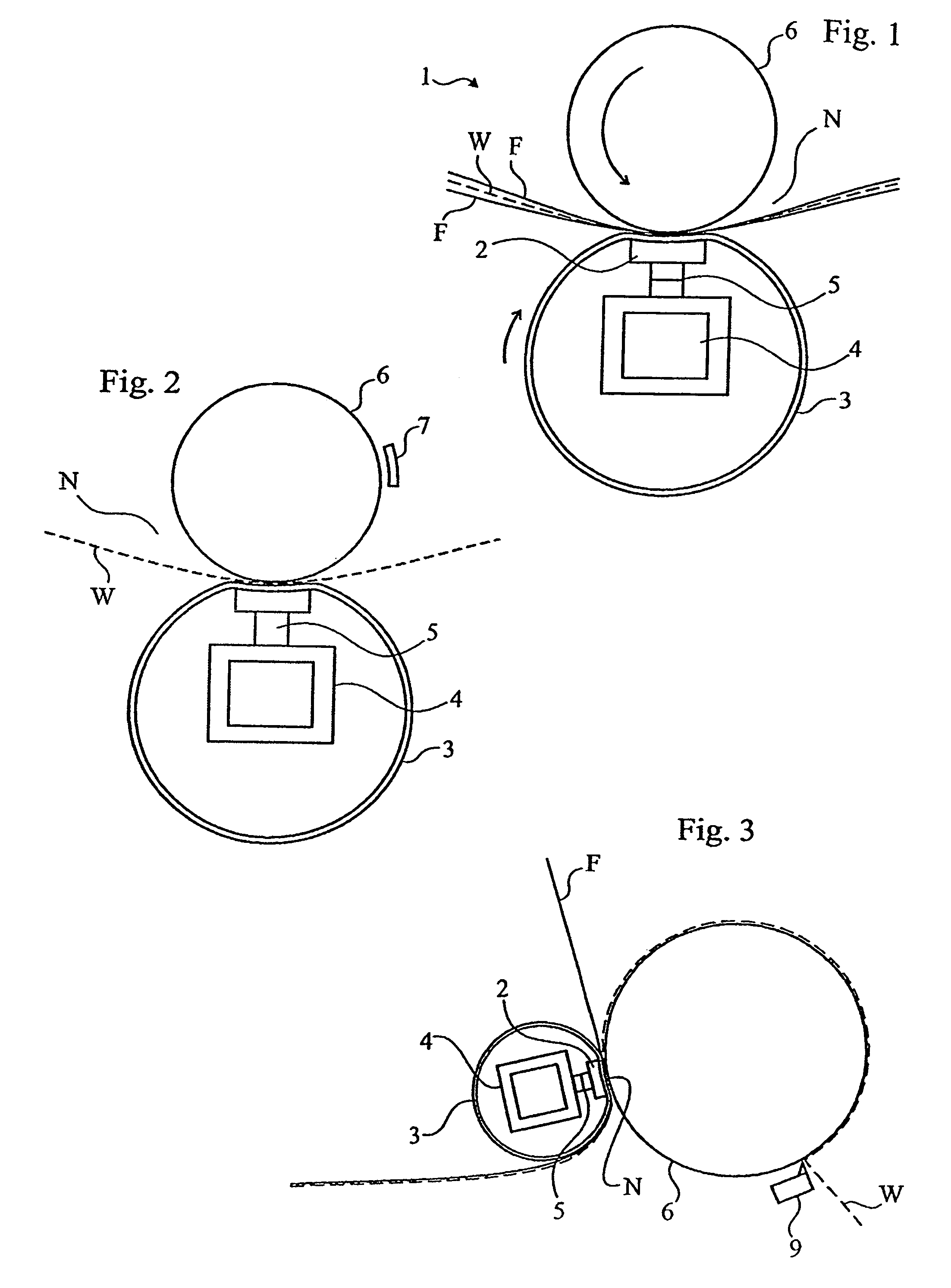
[0034]The present invention relates to a shoe press 1 for applying pressure to a fibrous web W. With reference to FIG. 1, the shoe press 1 comprises a concave press shoe 2 which is adapted to be juxtaposed with a backing member 6 such that the web W can be carried through a nip N defined therebetween. It should be understood that the press shoe 2 extends in a cross-machine direction (see FIG. 12) along substantially a full width of the web. The shoe press 1 further comprises a support 4 which supports the press shoe 2. The support 4 may be a cast beam such for example a cast I-beam. The support 4 can also be a welded box-beam 4. The press shoe 2 is movable in a loading direction toward the backing member 6 for applying pressure to the web. For moving the press shoe 2 toward the backing member 6, the shoe press comprises a plurality of articulated hydraulic actuators 5 that are spaced apart in the cross-machine direction along the press shoe 2. The actuators 5 thus form a row that ex...


PUM

PropertyMeasurementUnit
widthaaaaaaaaaa
widthaaaaaaaaaa
widthaaaaaaaaaa

Abstract

A shoe press 1 for applying pressure to a fibrous web W has a concave press shoe 2 adapted to be juxtaposed with a backing member 6. A plurality of articulated hydraulic actuators 5 are spaced apart in the cross-machine direction along the press shoe 2 to press the shoe toward a backing member. The actuators have first and second cylinders and a piston. The pistons and the cylinders have spherical surfaces adapted to be able to cooperate with each other.

Description

CROSS REFERENCES TO RELATED APPLICATIONS[0001]This application claims priority on European Patent App. No. 04102661.8, Filed Jun. 11, 2004, the disclosure of which is incorporated by reference herein.STATEMENT AS TO RIGHTS TO INVENTIONS MADE UNDER FEDERALLY SPONSORED RESEARCH AND DEVELOPMENT[0002]Not applicable.BACKGROUND OF THE INVENTION[0003]The present invention relates to shoe presses for applying pressure to a running web of paper, paperboard, or the like. More particularly, the present invention relates to a shoe press of the type having a support which supports a press shoe adjacent to a cylindrical backing member such that the press shoe and backing member form an extended nip therebetween, and having a hydraulic device for urging the press shoe toward the backing member to apply pressure to the web running through the nip. The shoe press of the present invention can be used for example as a dewatering press in the press section of a paper or paperboard machine, as an extend...

Claims


Application Information

Patent Timeline
Patent Type & Authority Patents(United States)
IPC IPC(8): D21F3/02D21F3/00D21G1/00
CPCD21F3/0218D21G1/006
Inventor BENGTSSON, ROLAND
Owner VALMET TECH INC
Why Eureka
Try Eureka