Reflector comprising a plurality of concave portions and liquid crystal display device including the same

a liquid crystal display device and reflector technology, applied in the field of reflectors, can solve the problems of difficult to achieve the desired reflection characteristics of the reflector, easy generation of interference pattern of light between the reflector etc., to achieve the effect of reducing the interference pattern of light between the pixels and the concave portion of the reflector, reducing the generation of moiré patterns, and reducing the change of reflectivity due to the viewing direction of the viewer

Inactive Publication Date: 2008-06-17
ALPS ALPINE CO LTD
View PDF17 Cites 1 Cited by
  • Summary
  • Abstract
  • Description
  • Claims
  • Application Information

AI Technical Summary

Benefits of technology

[0015]The present invention has been made in order to solve the above-mentioned problems, and provide a reflector and a liquid crystal display device in which the moiré effect is prevented while achieving the desired reflection characteristics.

Problems solved by technology

However, in the conventional liquid crystal display device, since the arrangement direction x of the pixel P formed in the liquid crystal display panel is equal to the axis direction L3 of the concave portion 128b, there is a problem in that an interference pattern of the light is apt to be generated between the reflector and the liquid crystal display panel, or moiré lines or rainbow color is apt to be generated.
When employing this structure, because the direction of the reflective surface is deviated, there was a problem that it is difficult to achieve the desired reflection characteristics of the reflector.

Method used


Image

  • Reflector comprising a plurality of concave portions and liquid crystal display device including the same
  • Reflector comprising a plurality of concave portions and liquid crystal display device including the same
  • Reflector comprising a plurality of concave portions and liquid crystal display device including the same

Examples


first embodiment

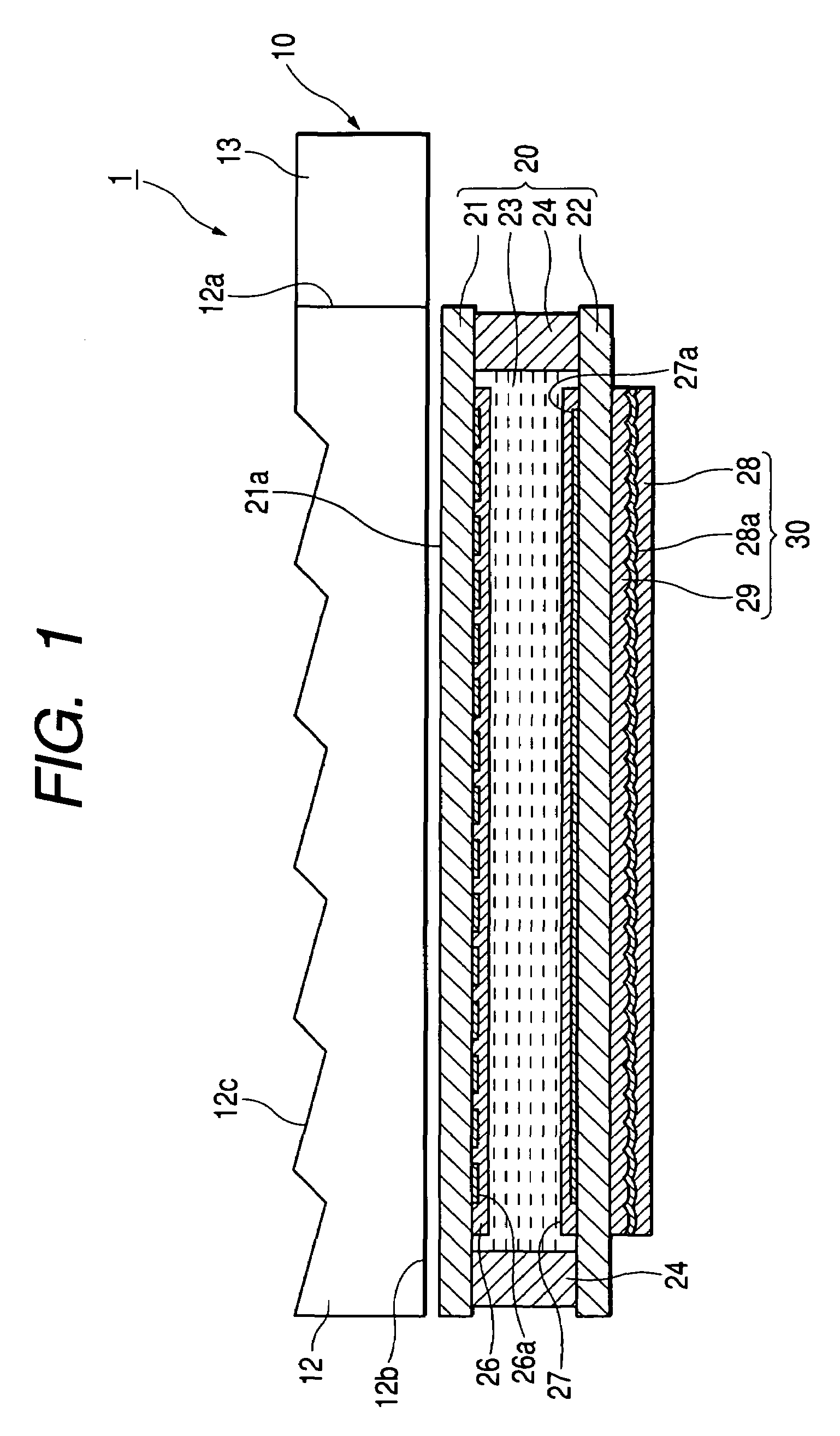
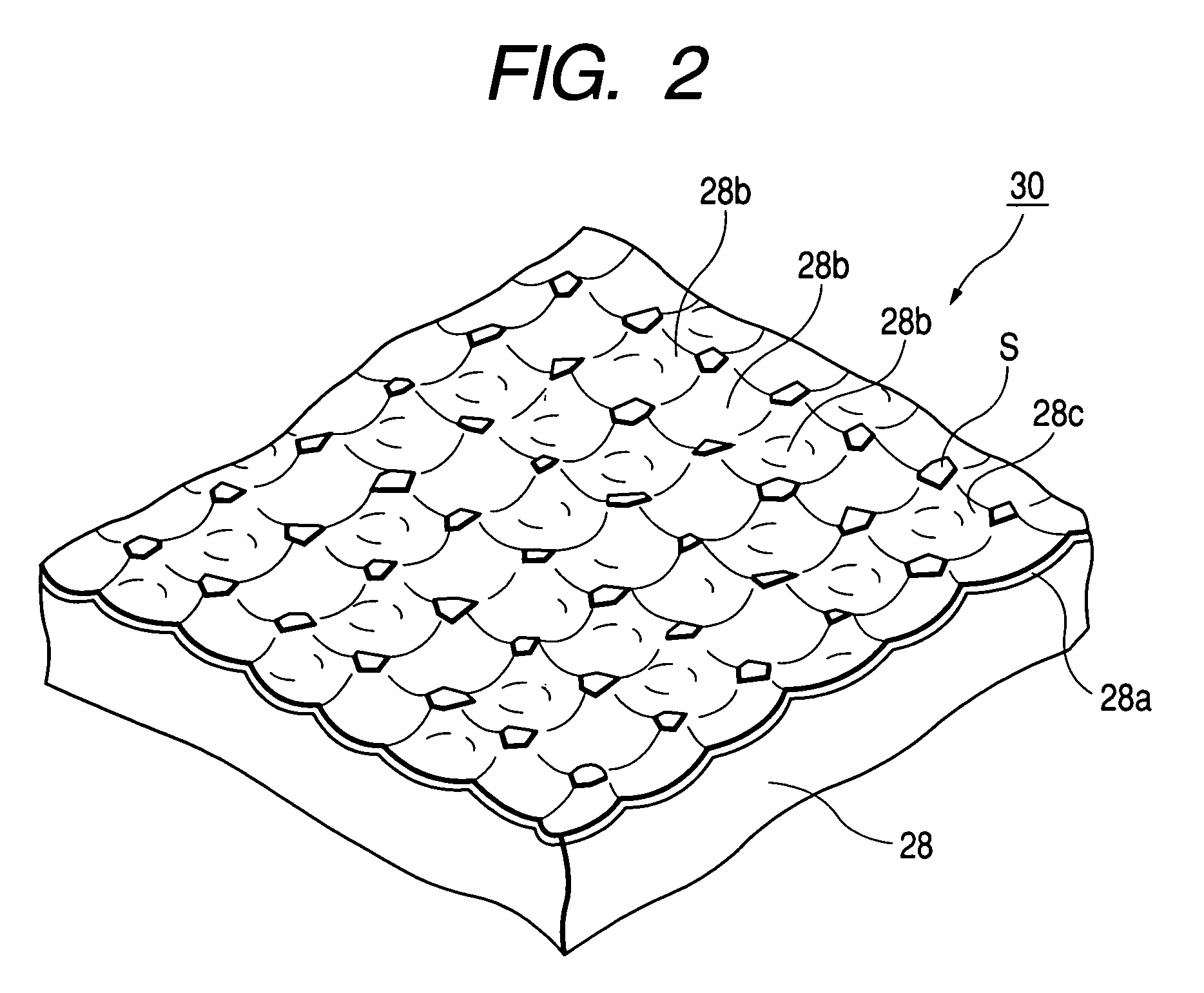
[0054]FIG. 1 is a schematic sectional view showing a liquid crystal display device according to a first embodiment of the present invention, and FIG. 2 is a perspective view of a reflector included in the liquid crystal display device.

[0055]As shown in FIG. 1, the liquid crystal display device 1 according to the present invention is a reflective liquid crystal display device generally comprising a liquid crystal display panel 20 and a front light unit 10 arranged on the viewing side of the liquid crystal display panel 20 (on the side which is to be viewed).

[0056]As shown in FIG. 1, the liquid crystal display panel 20 comprises a first substrate 21 and a second substrate 22 (a pair of substrates) adhered to each other by sealing material 24 and with a liquid crystal layer 23 sandwiched therebetween. Also, the outer surface of the first substrate 21 is a display surface 21a. The first substrate 21 and the second substrate 22 are composed of a transparent substrate such as a glass subs...

second embodiment

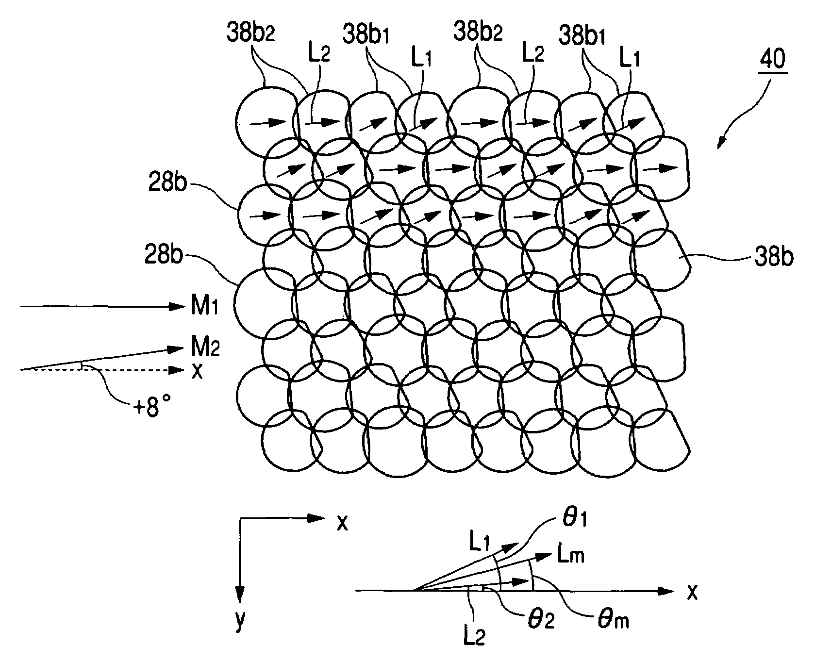
[0083]Next, a second embodiment of the present invention will be explained with reference to the drawings. FIG. 7 shows the concrete arrangement state of the concave portions 38b in the reflector 40 according to this embodiment. Also, the reflector 40 according to this embodiment is similar to the reflector 30 according to the first embodiment, except that the axis angles θ1, θ2 of the concave portions 38b and the average axis angle θm are different from the axis angles θ1, θ2 and the average axis angle θm according to the first embodiment. That is, in the first and second embodiments, the inner shape of the concave portion 38b, the material of the base member, and the material and thickness of the reflective film are equivalent.

[0084]Accordingly, in the below description, only the axis angles θ1, θ2 of the concave portions 38b and the average axis angle θm will be explained, and the other details will be omitted.

[0085]As shown in FIG. 7, the reflector 40 according to the present em...

third embodiment

[0095]FIG. 9 shows a schematic perspective view of the reflector according to the present embodiment, and FIG. 10 shows a schematic sectional view of the corresponding concave portion. Also, the structure of the reflector according to the present embodiment is equal to that of the reflector 30 according to the first embodiment shown in FIGS. 2, 3 and 4, except for the structure of the concave portion shown in FIGS. 9 and 10.

[0096]The reflector according to the present embodiment is characterized by reflection brightness that is asymmetrically distributed with respect to the specular angle of the incident light. In order to have such reflection characteristics, the reflector according to the present embodiment is formed so that the inner shape of the concave portion 48b is controlled as described below.

[0097]The reflector according to the present embodiment can be applied as a reflector characterized by a reflection brightness distribution that is asymmetrical with respect to the spe...


PUM

PropertyMeasurementUnit
average axis angle θmaaaaaaaaaa
axis angle θmaaaaaaaaaa
axis angleaaaaaaaaaa

Abstract

A reflector and a liquid crystal display device in which original reflection characteristics can be sufficiently accomplished and moiré patterns can be prevented are provided. A reflector 30 formed with a plurality of concave portions 28b1, 28b2 on one surface of a base member along one arrangement direction is employed. When defining the section passing through the deepest point of the concave portion as a first section and defining the section perpendicular to the first section at the deepest point as a second section, the concave portions 28b1, 28b2 have symmetrical shapes on the basis of the first section and have asymmetrical shapes on the basis of the second section. When defining the directions along the first section in the concave portions 28b1, 28b2 as axis directions L1, L2, each of the axis directions L1, L2 are not parallel with the arrangement direction, and the axis directions L1, L2 are set to two or more directions.

Description

[0001]This application claims the benefit of priority to Japanese Patent Application No. 2003-125356, herein incorporated by reference.BACKGROUND OF THE INVENTION[0002]1. Field of the Invention[0003]The present invention relates to a reflector and a liquid crystal display device having asymmetrical concave portions, and more particularly to a reflector capable of preventing the moiré patterns from being generated by orienting the axis of the concave portion in a particular direction.[0004]2. Description of the Related Art[0005]A reflective liquid crystal display device is a liquid crystal display device using illumination light such as solar light or a front light as a light source and is mainly used in a portable information terminal requiring low power. Also, as another example, there is a semi-reflective liquid crystal display device. This is a liquid crystal display device which operates in a transmission mode by lighting an internal back light unit when external light can not b...

Claims


Application Information

Patent Timeline
Patent Type & Authority Patents(United States)
IPC IPC(8): G02F1/1335G02B5/08G02B5/02G02F1/13357
CPCG02B6/0055G02F1/133553G02B6/0038G02F2001/133616G02F1/133616
Inventor YOSHII, KATSUMASAKANO, MITSURU
Owner ALPS ALPINE CO LTD
Why Eureka
Try Eureka