Organic light emitting element and method of manufacturing the same

Active Publication Date: 2009-09-17
MATSUSHITA ELECTRIC WORKS LTD +1
View PDF3 Cites 34 Cited by
  • Summary
  • Abstract
  • Description
  • Claims
  • Application Information

AI Technical Summary

Benefits of technology

[0013]The present invention solves the above-described problems, and its object is to provide an organic light emitting element which has a small angular dependence of the light emissio

Problems solved by technology

However, an organic light emitting element has a tradeoff between brightness and life, and has properties such that an increase in brightness to obtain a sharper image and brighter illumination light shortens its life.
However, an organic light emitting element has problems such as reduction in light use efficiency as well as view angle dependence and film thickness dependence of light emission brightness and light emission spectrum, which occur more noticeably in an organic light emitting element with a plurality of light emitting layers as described above.
These problems are caused e.g. by light interference effect or total reflection which causes a phenomenon of light confinement in high refractive index media such as the organic light emitting layer, the substrate and the electrodes.
This means that the film thickness tolerance, when manufacturing the organic light emitting element, is small, resulting in a risk that the manufacturing efficiency may be reduced.
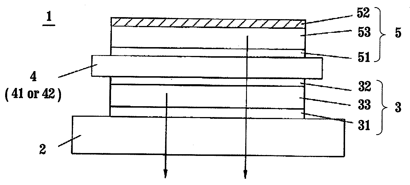
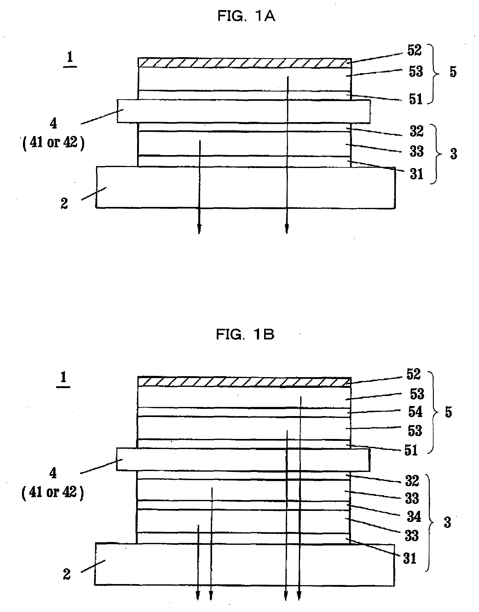
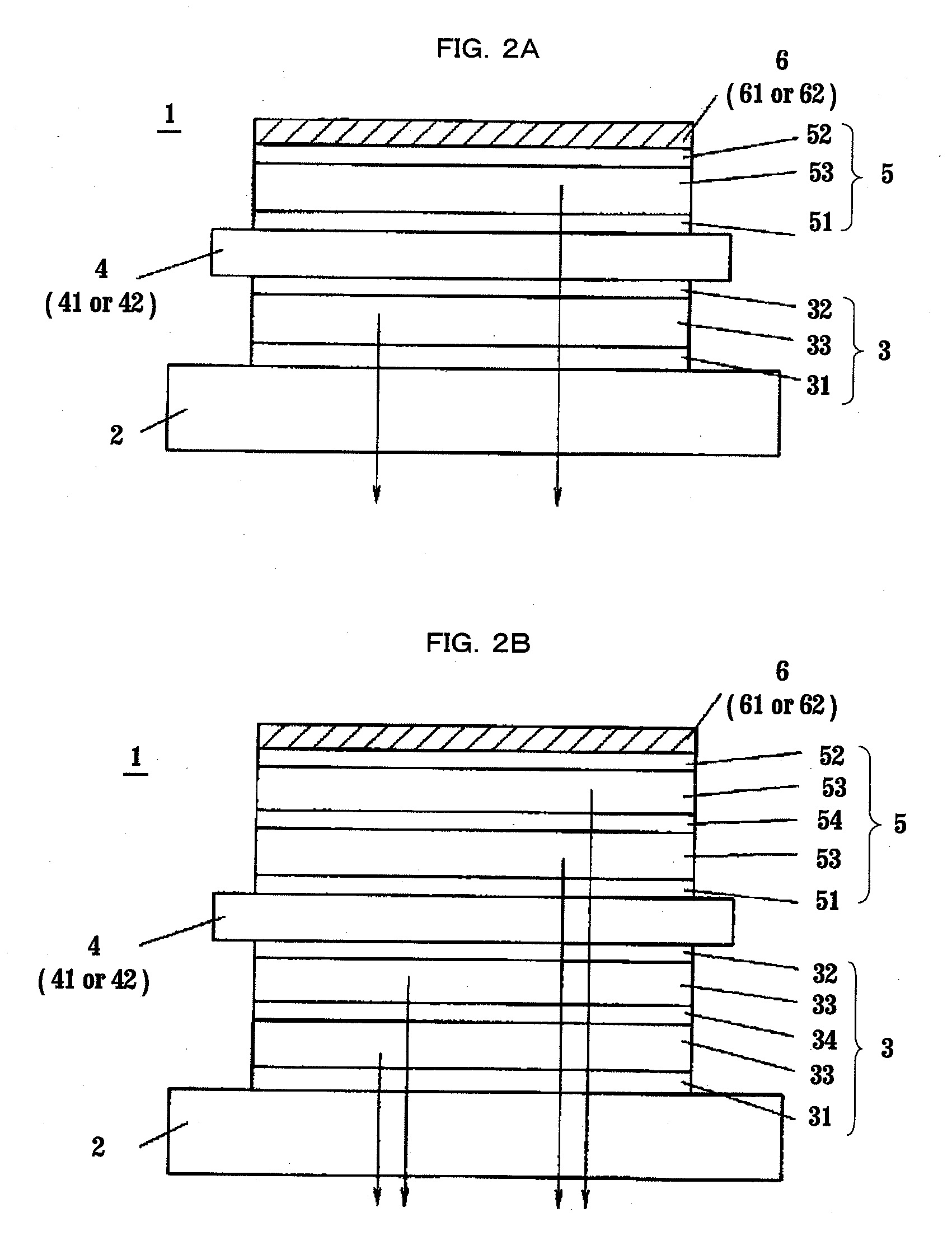
In particular, in an organic light emitting element formed by stacking a plurality of light emitting layers, an equipotential surface forming layer, a charge generation layer, and so on as described above, a slight deviation in optical properties (anomaly in film thickness and refractive index) occurring in one layer has a profound influence on the optical positions of the other layers, so that a highly accurate film thickness control is required, resulting in a risk of a high cost.
Thus, the organic light emitting element comprising the plurality of light emitting layers as described above does not have desirable properties with respect to the light emission spectrum and the view angle dependence, although it can achieve higher current efficiency and quantum

Method used


Image

  • Organic light emitting element and method of manufacturing the same
  • Organic light emitting element and method of manufacturing the same
  • Organic light emitting element and method of manufacturing the same

Examples


Embodiment Construction

[0037]Hereinafter, an organic light emitting element according to a first embodiment of the present invention will be described with reference to FIG. 1A. An organic light emitting element 1 (organic EL light emitting element) comprises a first light emitting unit 3, a light-transmitting insulating layer 4, and a second light emitting unit 5 which are stacked in this order on a substrate 2. The first light emitting unit 3 is formed by stacking a first light emitting layer 33 between two, first and second, electrodes 31, 32, in which one of the first and second electrodes 31, 32 serves as an anode, and the other as a cathode. Further, the second light emitting unit 5 is formed by stacking a second light emitting layer 53 between two, third and fourth, electrodes 51, 52, in which one of the third and fourth electrodes 51, 52 serves as an anode, and the other as a cathode, similarly as in the electrodes 31, 32. Here, among the first to fourth electrodes 31, 32, 51, 52, either the first...


PUM


Abstract

The present invention relates to an organic light emitting element comprising: a first light emitting unit comprising a light emitting layer between a pair of electrodes; and a second light emitting unit comprising a light emitting layer between a pair of electrodes. In the organic light emitting element, one electrode of the two pairs of electrodes which is positioned on the outermost side has light reflective properties, and the other electrodes have light transmission properties, while a light-transmitting insulating layer is provided between the first and second light emitting units. The insulating layer is formed in a thickness to prevent light emitted by the light emitting layer of the light emitting unit without the light reflective electrode from interfering with other lights, or formed to have properties of scattering the emitted light. Thus, the interference between the lights emitted by the light emitting layers and the other lights is reduced, so that in the organic light emitting element, the angular dependence of light emission spectrum is small, making it possible to adjust color.

Description

TECHNICAL FIELD[0001]The present invention relates to an organic light emitting element and a method of manufacturing the same which is used in a flat display panel, or as a light source for a backlight for a liquid crystal display apparatus, or for illumination, and so on.BACKGROUND ART[0002]An example of a known organic light emitting element, which is called organic electroluminescence element (organic EL element), is formed by stacking a transparent electrode as an anode, a hole transport layer, an organic light emitting layer, an electron injection layer, and an electrode as a cathode in this order on the surface of one side of a transparent substrate. When a voltage is applied between the anode and the cathode, electrons injected into the light emitting layer through the electron injection layer and holes injected into the light emitting layer through the hole transport layer are recombined in the light emitting layer to generate an excited state, thereby causing light emissio...

Claims


Application Information

Patent Timeline
IPC IPC(8): H01L33/00H01L21/28H01L51/50H05B33/02H05B33/10H05B33/12
CPCH01L27/3209H01L51/5268H01L51/006H01L51/0056H10K59/32H10K85/624H10K85/633H10K50/854H10K50/12
Inventor IDE, NOBUHIROKOMODA, TAKUYAKIDO, JUNJI
Owner MATSUSHITA ELECTRIC WORKS LTD
Why Eureka
Try Eureka